4-Bit BCD Synchronous Reset Counter VHDL Code
Advertisement
This page provides the VHDL source code for a 4 Bit BCD (Binary Coded Decimal) Synchronous Reset Counter. We’ll also look at the block diagram and truth table to understand its functionality.
Block Diagram and Truth Table
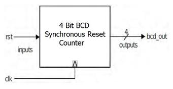
Here’s the block diagram illustrating the counter’s structure:
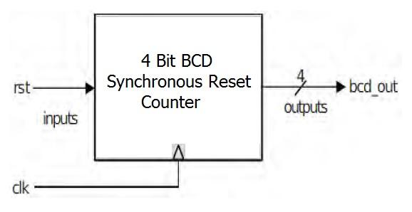
Image Alt Text: 4 Bit BCD Synchronous Reset Counter Block Diagram
And this is the truth table showing its counting sequence:
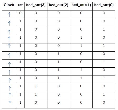
Image Alt Text: 4 Bit BCD Synchronous Reset Counter Truth Table
4 Bit BCD Synchronous Reset Counter VHDL Code
Here’s the VHDL code implementing the 4-bit BCD synchronous reset counter:
library ieee;
use ieee.std_logic_1164.all;
use ieee.std_logic_arith.all;
use ieee.std_logic_unsigned.all;

entity bcd_syn is
    port (
        clk, rst: in std_logic;
        bcd_out: out std_logic_vector(3 downto 0)
    );
end bcd_syn;

architecture behavioral of bcd_syn is
    signal div: std_logic_vector(22 downto 0);
    signal clkdiv: std_logic;
begin
    process (clk)
    begin
        if rising_edge(clk) then
            div <= div + 1;
        end if;
    end process;

    clkdiv <= div(22);

    process (clkdiv)
        variable temp: std_logic_vector(3 downto 0);
    begin
        if (rising_edge(clkdiv)) then
            if (rst = '0' or temp = "1001") then
                temp := "0000";
            else
                temp := temp + '1';
            end if;
        end if;
    end process;

    bcd_out <= temp;

end behavioral;
Explanation:
- Library Declarations: The code starts by including necessary libraries like
ieee.std_logic_1164for standard logic types,ieee.std_logic_arithandieee.std_logic_unsignedfor arithmetic operations on standard logic vectors. - Entity Declaration: The
entity bcd_syndefines the interface of the counter. It has two input ports:clk(clock) andrst(reset), both of typestd_logic. The output portbcd_outis a 4-bit standard logic vector representing the BCD output. - Architecture Declaration: The
architecture behavioral of bcd_syndescribes the behavior of the counter. - Clock Division: The first process divides the input clock (
clk) using a 23-bit counter (div). The most significant bit (div(22)) is used as the divided clock signalclkdiv. This is likely done to slow down the counting for testing or specific application requirements. - BCD Counting Logic: The second process is sensitive to the rising edge of the divided clock
clkdiv. It uses a variabletempof typestd_logic_vector(3 downto 0)to store the current BCD count.- Reset and Roll-Over: If the reset signal
rstis ‘0’ (active low reset) or if the current counttempis “1001” (9 in decimal), thentempis reset to “0000”. This ensures that the counter counts from 0 to 9 and then rolls over to 0. - Incrementing the Count: If the reset is not active and the count is not 9, the
tempvariable is incremented by 1 (temp := temp + '1';).
- Reset and Roll-Over: If the reset signal
- Output Assignment: Finally, the
bcd_outsignal is assigned the value of thetempvariable, providing the BCD output.
Advertisement
 RF
RF