 RF
RFN-Stage Johnson Counter: VHDL Code and Applications
Advertisement
This article explores the n-stage Johnson counter, including its VHDL code implementation, combinational logic diagram, and diverse applications. We’ll cover the basics of Johnson counters and delve into their practical uses.
There are two primary types of ring counters: Straight ring counters and Johnson counters.
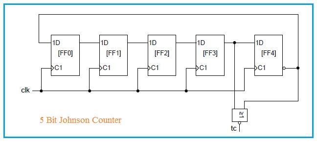
Figure 1: 5-bit Johnson Counter
Figure 1 illustrates a 5-bit Johnson counter, complete with a terminal count output, labeled “tc”. This output goes “HIGH” during the final counting state, “00001”, before resetting to the initial state of “00000”. Notably, there’s minimal logic between the output of one flip-flop and the input of the next. This characteristic enables Johnson counters to operate at high speeds.
The maximum operating frequency of a Johnson counter can be approximated by the following formula:
Where:
- represents the maximum propagation delay of the flip-flop output with respect to the active clock edge.
- is the setup time of the flip-flops.
Johnson Counter Applications
Johnson counters find application in a variety of scenarios:
- Decade Frequency Divider: A 5-stage Johnson counter is commonly used as a decade frequency divider.
- Multiphase Clock Signal Generator: They can serve as multiphase clock signal generators.
- High Accuracy Clocks: Johnson counters contribute to the creation of highly accurate clocks.
- Glitch-Free Outputs: They produce glitch-free symmetric outputs or count cycles.
- Stepper Motor Control: They are often used to drive stepper motors.
N-Stage Johnson Counter VHDL Code
Below is the VHDL code for an n-stage Johnson counter:
library ieee ;
use ieee.std_logic_1164.all;

-- The port description of the Johnson counter
entity johnson_counter is
    generic (n : integer := 5);
    port (
        clk    : in  std_logic ;
        areset : in  std_logic ;
        count  : out std_logic_vector (0 to n - 1) ;
        tc     : out std_logic
    );
end entity johnson_counter ;

architecture rtl of johnson_counter is
    -- Internal counter signal
    signal count_int : std_logic_vector (0 to n - 1) ;
begin
    -- The Johnson counter itself
    process (clk , areset ) is
    begin
        -- The reset is active high
        if areset = '1' then
            -- Set all counter bits to 0, nice VHDL trick
            count_int <= ( others => '0');
        elsif rising_edge ( clk ) then
            -- Shift the lot a stage and feed back the last one
            count_int <= not count_int (n - 1) & count_int (0 to n - 2) ;
        end if;
    end process ;

    -- The outputs
    count <= count_int ;

    -- tc high when counter is ...01 , where the dots should be all zeros.
    -- tc <= ( not count_int (n - 1) ) nor count_int (n - 2) ;
    -- tc <= '1' when count_int (n - 1) = '1' and count_int (n - 2) = '0' else '0';
    tc <= '1' when count_int (n - 2 to n - 1) = "01" else '0';
end architecture rtl ;
Advertisement


