4-Bit Binary Asynchronous Reset Counter in Verilog
Advertisement
This article provides Verilog source code for a 4-Bit Binary Asynchronous Reset Counter. We’ll cover the block diagram, truth table, and the Verilog code itself.
Block Diagram
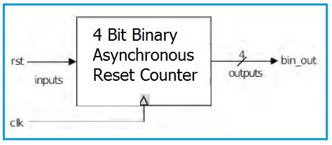
Here’s the block diagram of the 4-Bit Binary Asynchronous Reset Counter:

Image: 4 bit Binary Asynchronous Reset Counter Block Diagram
Truth Table
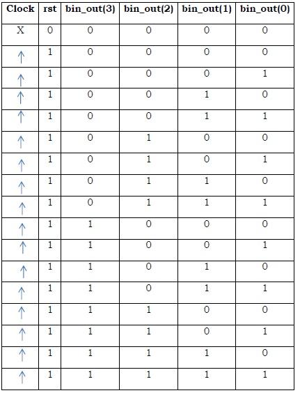
The following truth table shows the counter’s behavior:

Image: 4 bit Binary Asynchronous Reset Counter Truth Table
Verilog Code
Here’s the Verilog code for the 4-Bit Binary Asynchronous Reset Counter:
module bin_sync(
    clk,
    rst,
    bin_out
);

input clk, rst;
output [3:0] bin_out;

reg [3:0] bin_out;
reg [22:0] div;
reg clkdiv;

always @ (posedge clk)
begin
    div = div + 1'b1;
    clkdiv = div[22];
end

always @ (posedge( clkdiv))
begin
    if (rst == 0)
        bin_out = 4'b0000;
    else
        bin_out = bin_out + 4'b0001;
end

endmodule
Advertisement
 RF
RF


