Asynchronous FIFO Design: Verilog Code and Explanation
Advertisement
An Asynchronous FIFO (First-In, First-Out) design is a crucial component when you need to transfer data reliably between two systems operating with different, independent clock domains. Think of it as a secure bridge for your data! In essence, data is written into the FIFO memory using one clock, and read out using a completely separate clock that isn’t synchronized with the first. This is especially important when dealing with systems that can’t directly communicate due to timing differences.
Asynchronous FIFOs are commonly used to safely move data between these asynchronous clock domains.
A comprehensive PDF is available that walks you through designing an Asynchronous FIFO, complete with a test bench written in Verilog. It thoroughly covers the design process, including:
-
Block Diagram Breakdown: The PDF dissects the Asynchronous FIFO into its fundamental blocks. This includes:
- FIFO Memory: The heart of the system, storing the data.
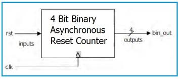
- Binary and Gray Counters: Essential for tracking read and write pointers, with Gray code used to minimize metastability issues when crossing clock domains.
- Synchronizers: Critical circuits that safely transfer the read and write pointers between the asynchronous clock domains. They mitigate the risk of metastability.
- Empty and Full Logic: Detecting when the FIFO is empty or full is vital to prevent underflow and overflow errors. This logic is carefully designed considering the asynchronous nature of the signals.
-
Output Waveforms: Clear waveforms illustrate the behavior of the FIFO, showing how data is written, read, and how the full and empty flags respond.
-
Verilog Test Bench: A complete test bench written in Verilog allows you to thoroughly verify the functionality of your Asynchronous FIFO design. This is key for ensuring it behaves as expected under various conditions.
-
Logic Synthesis Report: The synthesis report details the resources used and the performance achieved after synthesizing the Verilog code. This helps in optimizing the design for a specific target technology.
-
Schematic Generation: The PDF also includes the schematic representation of the FIFO derived from the Verilog code, providing a visual understanding of the circuit.
Advertisement
 RF
RF


