 RF
RFVHDL Code for a 1-to-4 Demultiplexer (DEMUX)
Advertisement
This page provides VHDL source code for a 1-to-4 DEMUX. We’ll cover the block diagram, truth table, and the VHDL code itself.
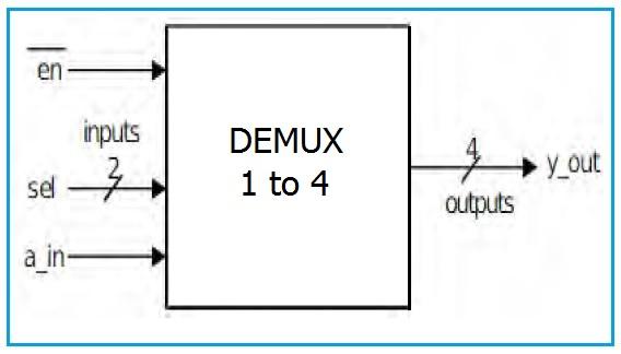
Block Diagram of 1-to-4 DEMUX
The following image illustrates the block diagram of a 1-to-4 DEMUX.
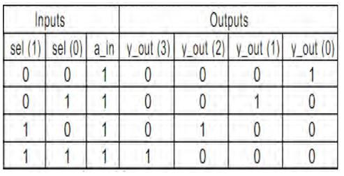
Truth Table of 1-to-4 DEMUX
The truth table below describes the operation of the 1-to-4 DEMUX.
1-to-4 DEMUX VHDL Code
Here’s the VHDL code for a 1-to-4 DEMUX. This code uses a case statement to route the input signal to the appropriate output based on the select lines.
library ieee;
use ieee.std_logic_1164.all;
use ieee.std_logic_arith.all;
use ieee.std_logic_unsigned.all;

entity demux1_4 is
    port (
        a_in  : in  std_logic;
        sel   : in  std_logic_vector (1 downto 0);
        y_out : out std_logic_vector (3 downto 0)
    );
end demux1_4;

architecture behavioral of demux1_4 is
begin
    process (a_in, sel)
    begin
        case (sel) is
            when "00" =>
                y_out (0) <= a_in;
                y_out (1) <= '0';
                y_out (2) <= '0';
                y_out (3) <= '0';
            when "01" =>
                y_out (0) <= '0';
                y_out (1) <= a_in;
                y_out (2) <= '0';
                y_out (3) <= '0';
            when "10" =>
                y_out (0) <= '0';
                y_out (1) <= '0';
                y_out (2) <= a_in;
                y_out (3) <= '0';
            when "11" =>
                y_out (0) <= '0';
                y_out (1) <= '0';
                y_out (2) <= '0';
                y_out (3) <= a_in;
            when others =>
                null; -- Optional: Handle unexpected select values
        end case;
    end process;
end behavioral;
Advertisement

