Verilog Code for 1 to 4 Demultiplexer
Advertisement
This page provides the Verilog source code for a 1 to 4 DEMUX (Demultiplexer). We’ll also cover the block diagram and truth table to help you understand how it works.
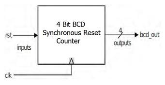
Block Diagram of 1 to 4 DEMUX
Here’s the block diagram illustrating the basic structure of a 1 to 4 DEMUX:

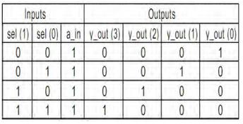
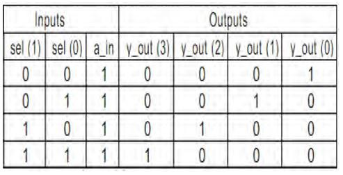
Truth Table of 1 to 4 DEMUX
The truth table below defines the behavior of the 1 to 4 DEMUX based on the select inputs:
1 to 4 DEMUX Verilog Code
Here’s the Verilog code for a 1 to 4 Demultiplexer:
module demux1_4(a_in, sel, y_out);
  input a_in;
  input [1:0] sel;
  output [3:0] y_out;
  reg [3:0] y_out;

  always @(a_in, sel)
  begin
    case (sel)
      2'b00: begin
        y_out[0]=a_in;
        y_out[1]= 1'b0;
        y_out[2]= 1'b0;
        y_out[3]=1'b0;
      end
      2'b01: begin
        y_out[0]= 1'b0;
        y_out[1]=a_in;
        y_out[2]= 1'b0;
        y_out[3]=1'b0;
      end
      2'b10: begin
        y_out[0]= 1'b0;
        y_out[1]=1'b0;
        y_out[2]=a_in;
        y_out[3]=1'b0;
      end
      2'b11: begin
        y_out[0]= 1'b0;
        y_out[1]= 1'b0;
        y_out[2]=1'b0;
        y_out[3]=a_in;
      end
      default: y_out=3'b000;
    endcase
  end
endmodule
Advertisement
 RF
RF
