8-to-3 Priority Encoder: Verilog Code
Advertisement
This page provides Verilog source code for an 8-to-3 encoder with priority. It includes the truth table, schematic, and the Verilog code itself.
Truth Table and Schematic
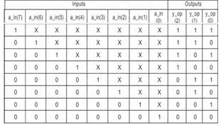
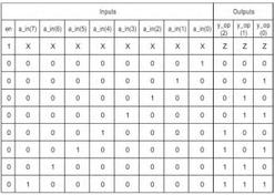
Here’s the truth table and schematic of the 8-to-3 encoder:

| En | I7 | I6 | I5 | I4 | I3 | I2 | I1 | I0 | Z2 | Z1 | Z0 | enx | V |
|---|---|---|---|---|---|---|---|---|---|---|---|---|---|
| V | 1 | X | X | X | X | X | X | X | 1 | 1 | 1 | 1 | 1 |
| 1 | 0 | 1 | 1 | 1 | 1 | 1 | 1 | 1 | 1 | 1 | 1 | 1 | 1 |
| 1 | 0 | 0 | 1 | 1 | 1 | 1 | 1 | 1 | 1 | 1 | 0 | 1 | 1 |
| 1 | 0 | 0 | 0 | 1 | 1 | 1 | 1 | 1 | 1 | 0 | 1 | 1 | 1 |
| 1 | 0 | 0 | 0 | 0 | 1 | 1 | 1 | 1 | 1 | 0 | 0 | 1 | 1 |
| 1 | 0 | 0 | 0 | 0 | 0 | 1 | 1 | 1 | 0 | 1 | 1 | 1 | 1 |
| 1 | 0 | 0 | 0 | 0 | 0 | 0 | 1 | 1 | 0 | 1 | 0 | 1 | 1 |
| 1 | 0 | 0 | 0 | 0 | 0 | 0 | 0 | 1 | 0 | 0 | 1 | 1 | 1 |
| 1 | 0 | 0 | 0 | 0 | 0 | 0 | 0 | 0 | 0 | 0 | 0 | 1 | 1 |
Note: In the truth table, ‘X’ represents a “don’t care” condition. The encoder prioritizes higher-order inputs.
Verilog Code
module enc8_3 (I, en, y, v);
  input [7:0] I;
  input en;
  output v;
  output [2:0] y;

  reg v;
  reg [2:0] y;

  always @ (en, I) begin
    if (en == 0)
      v = 0;
    else
      v = 1;

    if (I[7] == 1 && en == 1)
      y = 3'b111;
    else if (I[6] == 1 && en == 1)
      y = 3'b110;
    else if (I[5] == 1 && en == 1)
      y = 3'b101;
    else if (I[4] == 1 && en == 1)
      y = 3'b100;
    else if (I[3] == 1 && en == 1)
      y = 3'b011;
    else if (I[2] == 1 && en == 1)
      y = 3'b010;
    else if (I[1] == 1 && en == 1)
      y = 3'b001;
    else if (I[0] == 1 && en == 1)
      y = 3'b000;
    else
      y = 3'b000;
  end
endmodule
Explanation:
module enc8_3 (I, en, y, v);: Defines the module namedenc8_3with inputsI(8-bit input),en(enable), and outputsy(3-bit output), andv(valid output).input [7:0] I;: DeclaresIas an 8-bit input vector.input en;: Declaresenas a single-bit input (enable).output v;: Declaresvas a single-bit output (valid). It indicates if any of the inputs are high, and the encoder is enabled.output [2:0] y;: Declaresyas a 3-bit output vector, representing the encoded value.reg v;: Declaresvas a register.reg [2:0] y;: Declaresyas a register.always @ (en, I) begin ... end: This block executes whenever there is a change in either theeninput or any bit of theIinput.if (en == 0) v = 0; else v = 1;: If the enable inputenis 0, then the valid outputvis set to 0. Otherwise,vis set to 1.- The series of
if-else ifstatements checks each input bit fromI[7]down toI[0]. If a particular input bit is high (1) and the enable is high, the corresponding 3-bit code is assigned to the outputy. This implements the priority encoding, where higher-order inputs take precedence. else y = 3'b000;: If none of the inputsI[7:0]are high and the enable is high, the outputydefaults to3'b000.
Simulation Result
Here is an example simulation result:

This simulation result demonstrates the functionality of the 8-to-3 encoder. You can see how the output y changes based on the input I, and the v (valid) signal goes high when the encoder is enabled and there is a valid input.
Advertisement
 RF
RF


