2 to 4 Decoder Verilog HDL Code
Advertisement
This page provides the Verilog HDL code for a 2 to 4 decoder.
Symbol
Figure 1 shows the schematic symbol for a 2 to 4 decoder. The truth table is also provided below.

2 to 4 decoder schematic
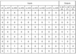
Truth Table
| E | Sel1 | Sel0 | Y3 | Y2 | Y1 | Y0 |
|---|---|---|---|---|---|---|
| 1 | 0 | 0 | 0 | 0 | 0 | 1 |
| 1 | 0 | 1 | 0 | 0 | 1 | 0 |
| 1 | 1 | 0 | 0 | 1 | 0 | 0 |
| 1 | 1 | 1 | 1 | 0 | 0 | 0 |
| 0 | X | X | 0 | 0 | 0 | 0 |
Verilog Code
module dec2_4 (a,b,en,y0,y1,y2,y3);
    input a, b, en;
    output y0,y1,y2,y3;

    assign y0= (~a) & (~b) & en;
    assign y1= (~a) & b & en;
    assign y2= a & (~ b) & en;
    assign y3= a & b & en;

endmodule
Simulation Result
The simulation result is shown in the following image.

2 to 4 decoder simulation result
Advertisement
 RF
RF


