RF
RFFlip-Flop Design Using LabVIEW VIs: SR, JK, T, and D
Advertisement
This article covers the design of various flip-flops using LabVIEW Virtual Instruments (VIs). The flip-flops discussed are SR, JK, T, and D flip-flops.
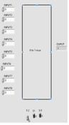
T Flip-Flop LabVIEW VI Block Diagram
The T flip-flop takes two inputs: the T input and the Clock input. It produces two outputs: Q(t) and the inverted Q(t), often denoted as Q’(t) or ¬Q(t).
Truth Table of T Flip-Flop:
| T Input | Q(t+1) |
|---|---|
| 0 | Q(t) |
| 1 | Q(t)’ |
Figure 1 shows the block diagram of the T flip-flop LabVIEW VI.

SR Flip-Flop LabVIEW VI Block Diagram
The SR flip-flop takes three inputs: S, R, and Clock. It generates two outputs: Q(t) and Q(t)’.
Truth Table of SR Flip-Flop:
| S Input | R Input | Q(t+1) |
|---|---|---|
| 0 | 0 | Q(t) |
| 1 | 0 | 1 |
| 0 | 1 | 0 |
| 1 | 1 | Not Allowed |
Figure 2 depicts the block diagram of the SR flip-flop LabVIEW VI.

D Flip-Flop LabVIEW VI Block Diagram
The D flip-flop has two inputs and two outputs.
Truth Table of D Flip-Flop:
| D Input | Q(t+1) |
|---|---|
| 0 | 0 |
| 1 | 1 |
Figure 3 illustrates the block diagram of the D flip-flop LabVIEW VI.

JK Flip-Flop LabVIEW VI Block Diagram
The JK flip-flop uses J, K, and Clock as inputs and produces Q(t) and Q(t)’ as outputs.
Truth Table of JK Flip-Flop:
| J Input | K Input | Q(t+1) |
|---|---|---|
| 0 | 0 | Q(t) |
| 1 | 0 | 1 |
| 0 | 1 | 0 |
| 1 | 1 | Q(t)’ |
Figure 4 presents the block diagram of the JK flip-flop LabVIEW VI.


Download Flip-Flop LabVIEW VI Source Code Files
- Download T flip-flop LabVIEW VI source code files
- Download SR flip-flop LabVIEW VI source code files
- Download D flip-flop LabVIEW VI source code files
- Download JK flip-flop LabVIEW VI source code files
- Download JK flip-flop LabVIEW SubVI source code files
Advertisement