RLC Tank Circuit Calculator: Resonant Frequency and Bandwidth
Advertisement
An RLC tank circuit, also known as a resonant circuit or a tuned circuit, incorporates all three passive electrical components: resistor (R), inductor (L), and capacitor (C). This circuit configuration allows for more versatile control and manipulation of resonant frequencies and impedance characteristics compared to circuits that use only LC elements.
The R, L, and C elements are arranged either in series or parallel configurations to form a series resonant circuit or a parallel resonant circuit. Let’s understand how an RLC tank circuit works.
-
Resistor (R): The resistor provides damping in the circuit, dissipating energy as heat. This helps control the sharpness of the resonance and the Q-factor (quality factor) of the circuit. The Q-factor determines how sharply the circuit resonates at its resonant frequency.
-
Inductor (L): The inductor stores energy in a magnetic field when current flows through it. It opposes changes in the current. In the RLC tank circuit, the inductor contributes to the energy storage necessary for resonance.
-
Capacitor (C): The capacitor stores energy in an electric field when a voltage is applied across its terminals. It opposes changes in voltage. In the RLC tank circuit, the capacitor contributes to the energy storage necessary for resonance.
RLC Tank Circuit Calculator
Example Calculation:
INPUTS:
- L = 200µH
- C = 20 nano Farad
- R = 100 Ohm
These calculations provide us with important parameters that describe the behavior of the RLC tank circuit, helping us understand its performance in various applications.
Applications:
RLC tank circuits find applications in various areas such as the following:
- Radio frequency (RF) circuits for tuning and filtering.
- Audio electronics for equalization and tone control.
- Power electronics for voltage regulation and filtering.
- Electronic oscillators and signal generators.
RLC Tank Circuit Formula or Equation
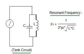
The following equation or formula is used for the RLC tank circuit Calculator. These equations are used to calculate resonant frequency and bandwidth.

In summary, an RLC tank circuit offers enhanced control over resonance characteristics compared to simpler LC tank circuits by incorporating a resistor to adjust damping and Q-factor. This versatility makes RLC tank circuits widely used in electronics for a range of tuning, filtering, and signal processing applications.
Advertisement
 RF
RF


