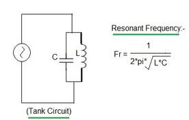
Series Resonance Frequency Formulas for LC, RC, and RLC Circuits
Advertisement
Resonance in electrical circuits happens when the circuit’s impedance (its opposition to current flow) hits its minimum. This results in the maximum possible current flow or voltage across the components. The resonant frequency is the specific frequency at which this condition occurs. Here’s how to calculate the resonant frequency in LC (inductor-capacitor), RC (resistor-capacitor), and RLC (resistor-inductor-capacitor) circuits under resonance conditions.
Series resonance formulas and resonant frequency calculators are very helpful in electrical and electronics work.
Series Resonance LC Circuit
In an LC circuit, an inductor (L) and a capacitor (C) are connected in series. Resonance occurs when the inductive reactance (XL) is equal to the capacitive reactance (XC). The formula to calculate the resonant frequency in an LC tank circuit is:
Where:
fLC= Resonant frequency in Hertz (Hz)L= Inductance of the coil in Henrys (H)C= Capacitance of the capacitor in Farads (F)π= Mathematical constant approximately equal to 3.14159
RC Circuit (Series Resonance)
In an RC circuit, a resistor (R) and a capacitor (C) are connected in series. Resonance happens when the circuit’s impedance is at its lowest. The resonant frequency formula for calculation in an RC tank circuit is:
Where:
fRC= Resonant frequency of the RC series circuit in Hertz (Hz)R= Resistance in OhmsC= Capacitance in Farads (F)π= Mathematical constant approximately equal to 3.14159
Series Resonance RLC Circuit
In an RLC circuit, a resistor (R), an inductor (L), and a capacitor (C) are connected in series. In this setup, resonance occurs when the total impedance (Z) reaches its minimum value. The formula to calculate the resonant frequency in an RLC circuit is:
In all of these formulas, you’ll notice that the resonant frequency is inversely proportional to the square root of the product of inductance (L) and capacitance (C) for LC and RLC circuits. For RC circuits, it’s inversely proportional to the product of resistance (R) and capacitance (C).
LC and RLC Resonance Frequency Calculator
You can use the calculator below to find the resonant frequency of both LC and RLC series tank circuits, since they use the same formula.
Note: Enter values in the INPUT boxes and press CALCULATE to check the OUTPUT.
Example of RLC and LC Resonance Frequency Calculation:
- Inputs: Inductance (Henry) = 0.002, capacitance (Micro-farads) = 12
- Output: Resonant frequency = 1027 Hz
RC Resonant Frequency Calculator
The following calculator can be used to calculate the resonant frequency of RC series tank circuits.
Example of RC Resonance Frequency Calculation:
- Inputs: Resistance (Ohms) = 1000, capacitance (Micro-farads) = 10
- Output: Resonant frequency = 15.92 Hz
Conclusion
Resonance frequency calculators and formulas are valuable tools for determining the resonant frequency of LC, RC, and RLC circuits. This is particularly useful in filter designs, radio frequency tuning circuit designs, and antenna design.
Advertisement
 RF
RF


