 RF
RFX.25 Protocol: Layers, Frame Structure, and X.21 Physical Layer
Advertisement
X.25 is a standard protocol suite widely used for packet-switched networks. It defines how data is transmitted across the network using different layers, namely the physical layer, frame layer, and packet layer. The physical layer (X.21) handles the hardware connections, while the frame layer (LAPB) ensures data link control, and the packet layer (PLP) manages end-to-end communication between devices. This tutorial delves into each layer of the X.25 protocol, the X.25 frame structure, and the roles and functionalities these layers play in enabling robust communication across networks.
Introduction
X.25 was developed by ITU-T and is a packet-switched wide area network (WAN). As shown in Figure-1, it serves as an interface between Data Terminal Equipment (DTE) and Data Circuit-Terminating Equipment (DCE) for operation on a public data network in packet mode.
X.25 is an end-to-end protocol. Users are typically unaware of packets passing between these terminals.
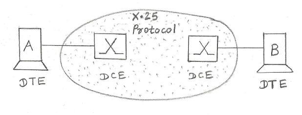
Figure-1: X.25 connection
X.25 defines the procedures and protocols needed to establish, maintain, and terminate connections. It also defines services to provide functions such as reverse charge, direct call, and delay control. It’s often referred to as a subscriber network protocol. It uses a virtual circuit approach to packet switching and asynchronous Time Division Multiplexing (TDM) to multiplex packets.
X.25 Protocol Stack
The X.25 protocol stack consists of three layers: the physical layer (X.21), the frame layer (LAPB), and the packet layer (PLP).
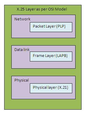
Figure-2: X.25 protocol stack
- Physical Layer: At this layer, X.25 specifies the X.21 protocol. It’s similar to other physical layer protocols such as EIA-232.
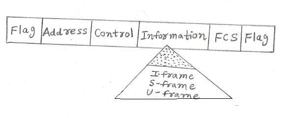
Figure-3: X.25 Frame structure
- Frame Layer: At this layer, X.25 provides data link control using LAPB (Link Access Procedure, Balanced), which is a subset of the HDLC (High-Level Data Link Control) protocol. LAPB is a bit-oriented protocol with the frame structure shown in Figure-3. The communication is point-to-point and in Asynchronous Balanced Mode. Two addresses are defined here:
00000001and00000011. The first is used for a command issued by DTE and in the response frame to this command. The second is used by DCE and in the response frame to this command.
There are three types of frames: I-frames, S-frames, and U-frames. _ I-frames are used to encapsulate PLP packets from the upper layer. _ S-frames are used for error control and flow control. * U-frames are used to set up and disconnect the connection between DTE and DCE.
There are three phases to establish communication between DTE and DCE:
*   **Link Setup:** First, the link needs to be set up between DTE and DCE before packet transfer takes place. Either DTE or DCE can set up the link by sending a SABM (Set Asynchronous Balanced Mode) frame, and the responding party sends a UA (Unnumbered Acknowledgement) frame to indicate that the link has been established.

*   **Transferring Data:** After the link is established, both parties can send and receive data/control frames using I-frames and S-frames.

*   **Link Disconnect:** When the network layer no longer needs the connection, either party can issue a DISC (Disconnect) frame to request disconnection, and the other party acknowledges by issuing a UA frame.
- Packet Layer: The network layer in X.25 is called the Packet Layer Protocol (PLP). It is responsible for establishing the connection, transferring data, and terminating the connection. It’s also responsible for creating virtual circuits and negotiating network services between two DTEs. As mentioned, the frame layer takes care of the connection between DTE and DCE, while the packet layer takes care of the connection between two DTEs.
PLP packets have a 3-4 byte header and optional information fields.
*   **GFI (General Format Identifier):** A 4-bit field.
    *   The first bit (Q bit, Qualifier) defines the source of control information: 0 for PLP and 1 for the upper layer protocol.
    *   The D bit (Delivery) defines which device should acknowledge the packet: 0 for the local DCE, 1 for the remote DTE.
    *   The last two bits indicate the size of the sequence number fields.
*   **LCN (Logical Channel Number):** A 12-bit field that identifies the virtual circuit chosen for the transmission.
*   **PTI (Packet Type Identifier):** Defines the type of packet, such as a data packet or control packet (RR, RNR, REJ, etc.).
Conclusion
Understanding the X.25 protocol and its layered structure is crucial for anyone working with packet-switched networks. The physical, frame, and packet layers work together to ensure reliable data transmission. By exploring the details of the X.25 frame structure and its layered functionality, network engineers can effectively design, troubleshoot, and optimize X.25 networks for various communication applications.
Advertisement


