MUX vs DEMUX: Understanding the Key Differences
Advertisement
This page covers the basics of MUX (Multiplexer) and DEMUX (De-Multiplexer) and highlights the differences between them.
MUX - Multiplexer
A multiplexer is a device or chip that selects one output from multiple input lines. The specific input line to be selected is determined by the signals applied to the selection lines. For example, if there are 8 input lines, then 3 selection lines are needed. This relationship follows the formula:
number of input lines = ,
Where n = number of selection lines.
Figure-1 (left side) shows a 4-to-1 multiplexer. Any one of the input lines (a, b, c, or d) is available at the output line (Z) based on the data programmed at the selection lines Sel(0,1).
 Figure-1 MUX DEMUX Process
DEMUX - Demultiplexer
The demultiplexer performs the reverse function of the multiplexer. It routes a single input signal to one of multiple output lines.
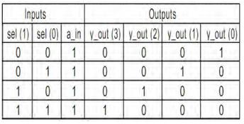
Figure-1 (right side) illustrates a 1-to-4 demultiplexer. Here, the input line ‘a’ can be routed to any one of the four output lines (Y). The selected output line is determined by the data available at the two ‘sel’ lines.
This principle was used in early telephone switching systems. Nowadays, this logic can be easily implemented in VHDL or Verilog and the code can be deployed on an FPGA device according to specific requirements.
Advertisement
 RF
RF


