 RF
RFMagneto-Optic Effect and Modulator Basics
Advertisement
This page covers the basics of the Magneto-Optic Effect and the Magneto-Optic Modulator. It describes the magneto-optic modulator’s working operation, particularly its use as an optical isolator based on the magneto-optic effect.
Introduction
Light modulation is the process by which its properties, such as amplitude, phase, pulse width, and direction, are changed during passage through a medium. Two different schemes are employed for light modulation: internal modulation and external modulation.
- Internal modulation uses a simple circuit to modulate the injected or driving current of the light sources (e.g., LED, Laser, etc.), as the light output from these sources is directly controlled by it.
- External modulation is the process by which the amplitude and phase of the light source can be modulated externally by electro-optic, magneto-optic, acousto-optic, or elasto-optic processes.
What is the Magneto-Optic Effect?
Similar to how an electric field can affect optical properties, the presence of a magnetic field can also influence the optical properties of selected materials through variations in the refractive index. This phenomenon is referred to as the magneto-optic effect.
Materials that exhibit this effect include quartz, ZnS, NaCl, crown glass, and flint glass. When a beam of light (with plane polarization) passes through these materials subjected to a magnetic field, its polarization rotates by an angle () as expressed below:
Where:
- = Verdet constant
- = Magnetic flux parallel to the direction of light propagation
- = Length of the magneto-optic material
This effect is referred to as the Faraday effect, and a modulator based on this effect is known as a Faraday rotator.
Verdet constant values for selected magneto-optic materials at a wavelength () of 590 nm are listed in the table below:
| Materials | Verdet constant (rad ** m-1 ** T-1) |
|---|---|
| Crown Glass | 6.4 |
| Flint Glass | 23.0 |
| NaCl | 9.6 |
| SiO2 (Quartz) | 4.0 |
| ZnS | 82.0 |
Let’s understand the working operation of the magneto-optic effect with the following diagram. The magneto-optic effect finds applications in fiber optic current sensors, high-power lasers, memories, etc.
Magneto-Optic Modulator Working Operation
The modulator based on the magneto-optic effect is known as a magneto-optic modulator. The following steps describe the magneto-optic modulator or Faraday rotator working operation:
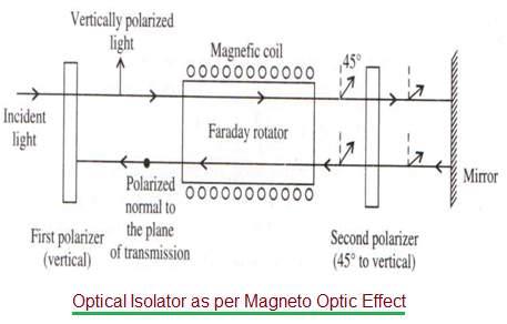
- As shown in the figure, a Faraday rotator and one pair of polarizers are used. In this arrangement, the left polarizer is vertically polarized, whereas the right polarizer is placed at 45° with respect to the vertical.
- When light passes through the left polarizer, it becomes vertically polarized.
- This vertically polarized light is then passed through the Faraday rotator, and it gets rotated by 45°, as shown.
- This 45° tilted light passes through the right polarizer without any further rotation, as it is already placed at a 45° tilt.
- The light gets reflected and made to pass again through the right polarizer. It does not undergo any rotation here, but when it enters the Faraday rotator, it goes through a 45° rotation.
- Now, the final return beam of light will have a total rotation of 90°. The plane of polarization of this return beam is at a right angle to the initially transmitted beam of light.
- Hence, the return beam gets blocked by the system.
- This arrangement is used to pass the light beam in one direction and block it in the other direction. Such a system is also known as an optical isolator.


