Low Pass vs. Band Pass Sampling: Key Differences Explained
Advertisement
This article breaks down the basics of sampling techniques for both low-pass and band-pass signals. We’ll explore the key differences between these two methods.
Low Pass Signal Sampling
 Figure 1: Low Pass Signal Sampling
As shown in Figure 1, low-pass signal sampling typically involves applying a low-pass analog filter before sampling the continuous signal. This filtering happens at a rate of Fs Hz. The input spectrum that we’re about to sample is symmetrical around zero Hz. Importantly, the spectral amplitude is zero above +B and below -B Hz.
When the signal is sampled at a rate of Fs samples per second, we observe spectral replications alongside the original input spectrum. The period of this replication is approximately Fs Hz.
For practical Analog-to-Digital (A/D) conversion, Fs is usually kept greater than 2B. This ensures that the spectral replications are separated at the folding frequencies of +/- Fs/2. This relationship, Fs > 2B, is famously known as the Nyquist Criteria.
The term Fs/2 is also referred to as the folding frequency. It’s crucial to note that frequency overlap, leading to aliasing, occurs when the sampling rate is too low, specifically when Fs/2 < B.
The Role of Anti-Aliasing Filters
In real-world scenarios, noise is always present along with the signal of interest, existing outside the frequency range of +/- B. Sampling this combined signal (Signal + Noise) without precautions would prevent overlapping between replications of our signal of interest, but it would also introduce noise components within the range of -Fs/2 and +Fs/2, ultimately corrupting the desired signal.
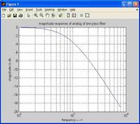
To combat this, we use an anti-aliasing filter before the A/D converter. This filter effectively attenuates any unwanted signal components that lie above +B and below -B. The dotted line in Figure 1 depicts a typical low-pass filter response. By employing this design, we can effectively avoid spectral aliasing at the output of the A/D converter.
Band Pass Signal Sampling
 Figure 2: Band Pass Signal Sampling
Figure 2 illustrates the Band Pass Signal Sampling process. This technique is used to sample continuous bandpass signals centered at a frequency other than 0 Hz. Essentially, bandpass sampling performs two key functions: digitization and frequency translation. These two functions together are often called sampling translation.
To avoid aliasing in bandpass sampling, the sampling frequency (Fs) must fall within a specific range:
( (2Fc-B)/m ) >= Fs >= ( (2Fc+B)/(m+1) )
Where:
m= any positive integer such that Fs >= 2BFc= Center FrequencyB= Bandwidth
Fs, determined according to this range, is then used for bandpass sampling.
Key Takeaways
In summary, the main difference lies in where the signal is located in the frequency spectrum. Low-pass sampling deals with signals centered around 0 Hz, while band-pass sampling handles signals centered at a non-zero frequency. Band-pass sampling also needs to adhere to a more complex sampling frequency range to avoid aliasing.
Advertisement
 RF
RF


