 RF
RFError Detection Methods: VRC, LRC, CRC and Checksum in computer networks
Advertisement
This article explores various error detection methods used in computer networking, including VRC, LRC, CRC, and Checksum. We’ll delve into how these techniques work and even look at a CRC error detection and correction example.
What is Error Detection and Correction?
Data transmission and processing are susceptible to errors stemming from factors like electrostatic interference, signal attenuation, distortion, and transmission losses. While LAN and optical cables minimize errors compared to wireless networks, errors can still occur in the form of single-bit errors or burst errors.
Types of Error:
- Single Bit Error: Only one bit within the data unit is altered. This is more common in parallel data transmission.
- Burst Error: Multiple consecutive bits are changed. This can be caused by impulse noise.
Principle of Error Detection:
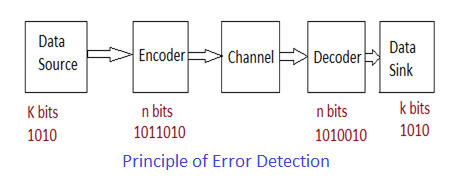
- When a frame is sent from transmitter to receiver, it can arrive either without errors or with errors.
- Error detection helps the receiver identify if a received block or frame contains errors.
- Upon detecting an error, the receiver requests the transmitter to re-transmit the frame.
- Error detection is achieved by adding redundant bits to each frame during transmission. Based on all the bits in the frame (data + error check bits), the receiver can detect errors in the frame.
Key Components:
- Message (or data) source: The source of the information in bits (K bits).
- Encoding process: Converts a block of k-bit information into an n-bit codeword, where n > k.
- Channel: The medium through which the n-bit codewords pass.
- Decoding process: Converts the n-bit received block back into a k-bit message.
- Message sink: The destination for the k-bit information.
Error Detection Methods
Here are the primary error detection methods used in networking:
- VRC Method
- LRC Method
- CRC Method
- Checksum Method
1. Parity Check or Vertical Redundancy Check (VRC)
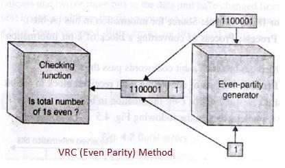
In VRC, a parity bit (a redundant bit) is added to each data unit. The parity bit is chosen such that the total number of 1s in the unit (including the parity bit) becomes even. The receiver then checks the received unit for even parity.
- If the receiver counts an even number of 1s, the data unit is considered valid.
- If the receiver counts an odd number of 1s, an error is detected, and the entire data unit is rejected.
Odd parity VRC can also be implemented where the total number of 1s should be odd before transmission.
2. Longitudinal Redundancy Check (LRC)
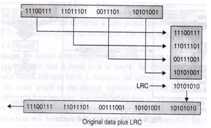
LRC organizes data into a table of rows and columns. Instead of sending a block of bits directly, it’s arranged into rows and columns. Parity bits are then calculated for each column, forming a new row of parity bits. This row of parity bits is appended to the original data before transmission.
3. CRC Error Detection and Correction
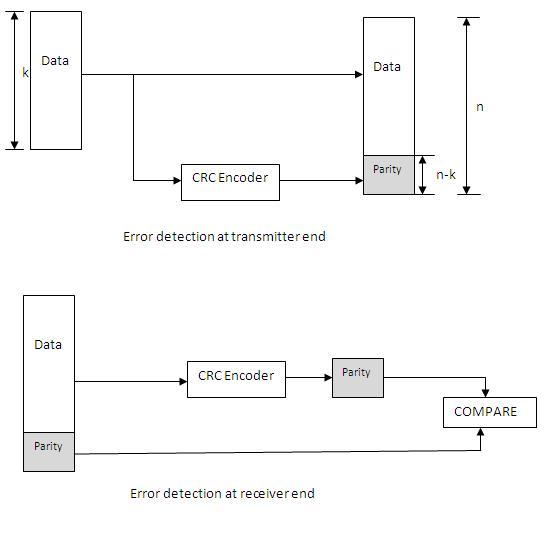
CRC (Cyclic Redundancy Check) involves a more complex calculation. At the transmitter, CRC bits are calculated based on the data block and appended to the data.
At the receiver, the CRC is recalculated based on the received data block and compared with the received CRC. If the calculated CRC matches the received CRC, the frame is considered error-free. If they don’t match, an error is detected.
As shown in the figure above, k bits are passed to the encoder to generate parity bits (n-k). These parity bits are added to the input data bits and are transmitted as n bits.
At the receiver, the parity bits along with the data bits are passed to the encoder. From the data part CRC is again computed and will be compared with the received CRC bits. Based on this comparison, the receiver determines if the data is corrupted or not. This process is called error detection and correction.
4. Checksum Method
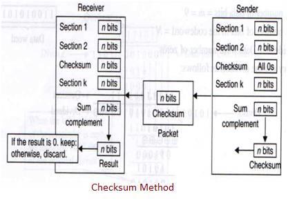
This method uses two main components: a checksum generator and a checksum checker.
Transmitter (Checksum Generator):
- The data unit is divided into equal segments of
nbits (typically 16 bits). - These segments are added together using one’s complement arithmetic, resulting in an
n-bit sum. - The sum is then complemented, and this complemented value (the checksum) is appended to the original data unit as redundant bits.
- The extended data unit is transmitted. So if the sum of the data segment is equal to T, the checksum will be -T.
Receiver (Checksum Checker):
- The receiver divides the received data unit in the same way.
- It adds all the segments together, including the checksum, and then complements the result.
- If the extended data unit is intact, the total value found by adding all data segments and the checksum should be zero.
- If the result is not zero, the packet contains an error, and the receiver rejects it.
Summary : VRC (Vertical Redundancy Check) adds a parity bit to each byte for simple single bit error detection. LRC (Longitudinal Redundancy Check) uses parity across multiple bytes, improving error detection across rows of data. CRC (Cyclic Redundancy Check) uses polynomial division for robust error detection, suitable for burst errors. Checksum sums data segments and sends the result along with the data to verify integrity at the receiver.
Advertisement


