Low Pass IIR Butterworth Digital Filter MATLAB Code
Advertisement
This section provides MATLAB source code for a BUTTERWORTH IIR (Infinite Impulse Response) digital filter, specifically a Low Pass IIR filter implementation. IIR digital filters operate on digital samples, utilizing current and past input samples, as well as previous output samples, to generate the current output sample.
IIR Filter Specifications
When designing an IIR filter, particularly one of the Butterworth type, consider the following specifications:
INPUT:
- Passband Ripple (Rp): The maximum allowable variation in the passband.
- Stopband Ripple (Rs): The minimum required attenuation in the stopband.
- Passband Edge Frequency (Wp): The frequency that defines the edge of the passband.
- Stopband Edge Frequency (Ws): The frequency that defines the start of the stopband.
- Sampling Frequency (Fs): The rate at which the analog signal is sampled.
- Filter Order (n): The complexity of the filter, influencing its performance.
- Filter Coefficients (b, a): The numerator (b) and denominator (a) coefficients of the filter’s transfer function.
OUTPUT:
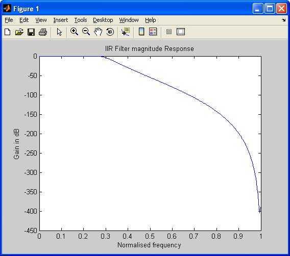
- Magnitude Response: How the filter attenuates or amplifies different frequencies.
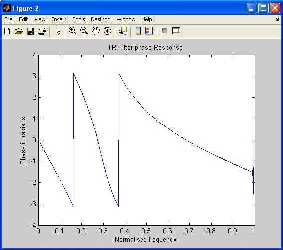
- Phase Response: The phase shift introduced by the filter at different frequencies.
MATLAB Code
The following MATLAB code demonstrates the design and implementation of a Low Pass IIR Butterworth filter:
clc;
close all;
clear all;
format long

% Entering Input parameters
rp=input('enter the passband ripple(Example:0.5):');
rs=input('enter the stopband ripple(Example:60):');
wp=input('enter the passband freq(Example:1300):');
ws=input('enter the stopband freq(Example:2600):');
fs=input('enter the sampling freq(Example:10000):');

% IIR MATLAB Function main part
w1=2*wp/fs;
w2=2*ws/fs;
[n,wn]=buttord(w1,w2,rp,rs);
[b,a]=butter(n,wn);
w=0:.01:pi;
[h,om]=freqz(b,a,w);
m=20*log10(abs(h));
an=angle(h);

figure;
plot(om/pi,m);
title('IIR Filter magnitude Response');
ylabel('Gain in dB');
xlabel('Normalised frequency');

figure;
plot(om/pi,an);
title('IIR Filter phase Response');
xlabel('Normalised frequency');
ylabel('Phase in radians');
Explanation
-
Input Parameters: The code prompts the user to enter the required filter specifications (passband ripple, stopband ripple, passband frequency, stopband frequency, and sampling frequency).
-
Normalization: The passband and stopband frequencies are normalized by the Nyquist frequency ().
-
buttordFunction: Thebuttordfunction determines the minimum filter order (n) and the Butterworth cutoff frequency (wn) required to meet the specified ripple and attenuation requirements. -
butterFunction: Thebutterfunction calculates the numerator (b) and denominator (a) coefficients of the Butterworth filter transfer function based on the order and cutoff frequency. The transfer function is represented as: -
Frequency Response: The
freqzfunction calculates the frequency response (h) of the filter at various frequencies (w). -
Magnitude and Phase Response: The magnitude (in dB) and phase of the frequency response are calculated and plotted.
INPUT and OUTPUT of IIR filter


Advertisement
 RF
RF


