RF Phase Shifter Basics and Types for Phased Array Antennas
Advertisement
This article covers RF phase shifter basics and RF phase shifter types used in phased array antennas and for other applications.
What is an RF Phase Shifter?
An RF (Radio Frequency) phase shifter is a device that shifts the phase angle of an input RF signal while keeping its amplitude constant.
Based on their control mechanisms and mechanical constructions, phase shifters can be categorized into:
- Analog phase shifters
- Digital phase shifters
- Mechanical phase shifters
Analog Phase Shifter
In this type, the phase shift is controlled using an analog control voltage.
Digital Phase Shifter
Here, the phase shift is controlled using digital data bits, typically through a microcontroller, microprocessor, or computer interface. USB and Ethernet-controlled phase shifters fall under this category and are often referred to as programmable phase shifters.
Mechanical Phase Shifter
In this type, the phase shift is manually controlled by tuning a knob.

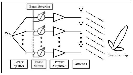
The figure above depicts digital phase shifters used in a phased array transmitter system. These phase shifters are used to change the phase angle of individual beams provided to individual antennas used in an antenna array. Hence it generates the required beamformed output as per system requirements.
There are four main types of array antennas:
- Linear array
- Planar array
- Circular array
- Conformal array
The classification is based on the position and shape of the antenna elements.
RF Phase Shifter Specifications
When selecting an RF phase shifter, consider these specifications:
- Phase range: (in degrees)
- Phase shifter control type: (Analog Voltage, Digital bits, Mechanical knob, Programmable control)
- Insertion Loss: (dB)
- Operating frequency range
- Power at input and output
- Supply voltage
- Package type: (Surface mount, module, benchtop, rackmount)
Comparison Between RF Phase Shifter Types
RF phase shifters can also be classified based on the materials used in their construction and their design methods. These include ferroelectric phase shifters, MMIC-based phase shifters, ferrite phase shifters, and MEMS phase shifters.
The following table highlights the differences between these types based on various comparison parameters:
| Features | Ferroelectric based | MMIC (Semiconductor based) | Ferrite based | MEMS based |
|---|---|---|---|---|
| Power handling | > 1 Watt | Tens of Watts | KW | < 50 mWatt |
| Linearity | IMD (Intermodulation distortion) intersect at +60 dBm | IMD (Intermodulation distortion) intersect between +35 to +40 dBm | IMD (Intermodulation distortion) intersect at +80 dBm | |
| Switching speed | Intrinsically fast, in ns range | Fast, < 10-9 seconds | 10 to 100 µs | 10 to 100 µs |
| DC power consumption | Low, µW range (<1 µA current) | Low, <10 mWatt | High, 10 Watt range | Negligible |
| RF loss | Approx. 5 dB/36o @ K band | Approx. 2 dB/bit @ Ka band | < 1 dB / 360o @ X band | Approx. 2.3 dB/337.5o @ Ka band |
| Size | Very small | Small | Large | Small |
| Reliability | Good | Very good | Excellent | Good |
| Cost | Low | Expensive | Very expensive | Low |
Reference: Information provided in the table has been derived from a PDF document on “Array Phase Shifters: Theory and Technology”
Source: NASA Center for Aerospace Information.
Advertisement
 RF
RF


