PIN Diode as RF Phase Shifter
Advertisement
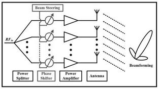
A PIN diode can be used as an RF phase shifter in electronic circuits. A phase shifter is a device that changes the phase of an incoming RF signal. Phase shifter circuits are useful in various applications such as beamforming systems, antenna arrays, and communication systems.
In a PIN diode-based RF phase shifter, the diode is biased using DC voltage. By controlling the bias voltage, the resistance of the diode can be varied. This, in turn, affects its capacitance. This change in capacitance leads to a change in the phase of the RF signal passing through the diode.
PIN Diode RF Phase Shifter Circuit Working
The basic RF phase shifter consists of a PIN diode, a biasing circuit, and a matching network. The PIN diode is the key component that controls the phase shift. It is connected in series with the RF signal path.
The PIN diode is biased using a DC voltage source. The bias voltage determines the resistance of the diode and, consequently, its capacitance.
To ensure proper impedance matching and minimize signal reflections, a matching network is often added before and after the PIN diode.
Let’s understand how a PIN diode can be used in an RF phase shifter circuit:
- When a bias voltage is applied to the PIN diode, its resistance changes, which affects the capacitance as well.
- The PIN diode can be biased in two modes: a low resistance state (ON) and a high resistance state (OFF).
- In the ON state, the diode has lower capacitance, which allows the RF signal to pass through with minimal phase shift.
- In the OFF state, the diode has higher capacitance, causing a phase shift in the RF signal.

The phase shift introduced by the diode can be adjusted by controlling the bias voltage. The phase shift can be precisely controlled based on the characteristics of the PIN diode and biasing circuit design.
The circuit diagram depicts a PIN diode phase shifter with driver amplifier connections. There will be one driver part for each bit.
Advantages
Following are the benefits or advantages of PIN diode phase shifters:
- It offers continuous and smooth phase shifting without any mechanical components.
- It offers a fast response time for dynamic phase adjustments.
- It offers a wide frequency range.
Limitations
- The achievable phase shift range might be limited by the characteristics of the PIN diode and available biasing voltage range.
- Careful design is required to minimize signal distortion and maximize performance.
Conclusion
In summary, PIN diode-based RF phase shifters provide a convenient and efficient way to control the phase of RF signals in electronic circuits such as beamforming, antenna arrays, and so on.
Advertisement
 RF
RF


