RF Transformer vs RF Balun: Understanding the Differences
Advertisement
In RF and wireless communication systems, RF transformers and RF baluns play critical roles in signal transformation and impedance matching. While both devices are essential for managing RF signals, their functions, applications, and design principles differ significantly.
This guide explores the distinctions between RF transformers and RF baluns, shedding light on their unique features, advantages, and use cases to help you select the right component for your RF applications.
What is an RF Transformer?
The purpose of an RF transformer is to match impedance between different parts of an RF circuit. It can step up or step down the impedance, which allows efficient power transfer between various components. The RF transformer operates on the principle of mutual inductance. It typically has primary and secondary windings, and the turns ratio between these windings determines the impedance transformation.
The turns ratio () of a transformer is the ratio of the number of turns in the primary winding () to the number of turns in the secondary winding (). The equation can be expressed as follows:

The turns ratio and voltage and current transformations can be expressed as follows. Here , , and are primary voltage, secondary voltage, primary current and secondary current respectively.
The impedance transformation equation can be expressed as follows:
Applications of RF Transformer
RF transformers are commonly used in the following applications:
- For impedance matching between different parts of RF circuits to ensure optimal power transfer.
- For coupling signals between various parts of RF system while maintaining impedance continuity.
- To provide isolation between different sections of a circuit.
- For voltage and current transformations
- Used in balanced modulators and demodulators to process signals efficiently.
Application of Transformer (as Intermediate Frequency Transformer in Radio Receivers)
Here, an RF signal is received by an antenna and mixed with an LO (Local Oscillator) to produce an IF (Intermediate Frequency). Here a transformer helps in efficiently coupling and transforming the intermediate frequency signal. Unwanted frequencies are being filtered out and bandwidth is narrowed down for further processing. The transformer assists in impedance matching between the mixer stage and subsequent IF amplification stages. This ensures maximum power transfer and signal fidelity.
What is an RF Balun (Balanced to Unbalanced Transformer)?
The purpose of a balun is specifically designed to convert signals between balanced and unbalanced formats. It is used when connecting balanced transmission lines (e.g., twisted pair cables) to unbalanced systems (e.g., coaxial cables). Baluns can use various configurations, such as transformer-based, transmission line-based, or hybrid designs. The primary goal is to transform the impedance from a balanced configuration to an unbalanced one or vice versa.
Baluns are frequently used in RF systems to interface between balanced antennas (e.g., dipole antennas) and unbalanced transmission lines (e.g., coaxial cables). They help prevent issues like common-mode noise and improve signal integrity.
Applications of RF Balun
Baluns are commonly used in the following applications:
- To connect balanced antennas (e.g. dipole) to unbalanced transmission lines
- Interface between balanced transmission lines (e.g. twin lead or twisted pair) and unbalanced transmission lines (e.g. coaxial cables).
- Helps to reduce common mode noise in transmission lines
- Used in audio and video systems for balanced and unbalanced conversion of signals.
- Baluns can be used in PoE (Power Over Ethernet) systems to separate power and data signals.
Application #1 of RF Balun
A balun is used to match the balanced nature of a dipole or other antenna with the unbalanced characteristic of the coaxial feedline. The following TV connector houses a balun which converts a 75 Ohm line to a 300 Ohm line impedance and vice versa.

Application #2 of Balun
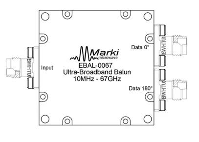
The figure depicts a broadband balun from Marki Microwave. They are passive reciprocal devices. They are used for either single ended to differential or differential to single ended conversion.

It supports a 10 MHz to 67 GHz frequency range and is used for 50 ohm to 100 ohm conversion and vice versa.
Difference between RF Balun and Transformer
The following table summarizes the difference between an RF Balun and a transformer with respect to various specifications or features.
| Parameters | RF Transformer | RF Balun |
|---|---|---|
| Purpose | Used to match impedance between different components. | Used for conversion between balanced to unbalanced formats. |
| Working operation/principle | Works on principle of mutual inductance | Supports various configurations viz. transformer based, transmission line based, hybrid |
| Signal integrity | Improves power transfer efficiency | Minimizes common mode noise, enhances signal integrity |
| Applications | Impedance matching, signal coupling, isolation | Connecting balanced antennas to unbalanced systems, reducing common mode noise |
| Use cases | RF circuit design, signal conditioning | Antenna systems, RF Transmission lines |
| Examples | Broadband transformers, IF transformers | 1:1 Balun, 4:1 Balun, Ferrite core balun |
Conclusion
Both RF transformers and RF baluns are indispensable components in RF and wireless systems. RF transformers excel in signal isolation, impedance matching, and voltage step up/step down applications, while RF baluns are specifically designed to convert balanced signals to unbalanced ones and vice versa. Understanding their differences enables one to make informed decisions when designing and troubleshooting RF circuits. Whether your focus is on signal clarity or compatibility, choosing the correct device is key to achieving optimal system performance.
Advertisement
 RF
RF


