Acousto Optic Modulator (AOM) Basics and Working
Advertisement
This page covers Acousto optic modulator basics, including its construction, and describes Acousto optic modulator working operation.
Introduction: Acousto optic modulators work based on the acousto-optic effect. This effect deals with the modulation of optical properties through variation in the refractive index of the medium under the influence of an acoustic wave.
What is an Acousto Optic Modulator?

- It works based on the acousto-optic effect, which deals with the modulation of optical properties by varying the refractive index of a medium under the influence of an acoustic wave.
- Refractive index variation under the photoelastic effect is observed in all materials. However, materials such as LiNbO3 and PbMoO4 have shown potential applications.
- Fiber-coupled acousto optic modulators have become more popular. They have three terminals: laser input, laser output, and RF Input.

- The Q-factor determines the interaction regime between the acoustic wave and the laser beam.
- The condition of Q >> 1 is known as the Bragg regime. In this condition, at one particular incidence angle ΘB, only one diffraction order is produced, and the rest of the orders are annihilated by destructive interference.
- Most acousto-optic devices operate in this Bragg regime.
Acousto Optic Modulator Working Operation

The following steps describe acousto optic modulator (AOM) working operation:
-
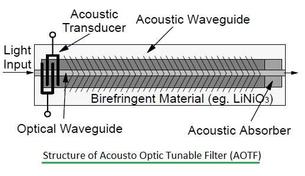
It works based on the photo-elastic effect or interaction of acoustic sound waves and a light signal in a crystalline material. An acoustic wave is generated in the crystal by the application of an RF drive signal into a piezo-electric transducer, which is used at the “RF IN” port.
-
Due to compression and refraction, periodic changes occur to the refractive index. As a result, the light input signal is diffracted into a number of orders at the output. AO modulators are traveling wave devices, unlike diffraction gratings.
-
An absorber is used at the opposite end of the “RF IN” terminal or port. It’s placed to direct all the acoustic waves towards the absorbing surface and is designed such that remaining reflections do not create any secondary diffraction.
-
Acousto optic modulators are designed to maximize the diffraction of the input laser beam into a single 1st order position. In this condition, the AO modulator device is said to be operating in the Bragg regime.
-
It requires correct alignment of the AO device, and the drive power is adjusted to be near or below the RF saturation level.
-
In Figure 2, the Bragg angle is expressed as follows: Θ Bragg = (λ * f ) / (2 * V). This angle is in the plane of deflection and relative to the normal from the input optical surface.
-
The output separation angle between the zeroth order and the first order is expressed as follows: Θ sep = λ * f /V
Where:
- f = RF frequency
- λ = wavelength
- V = Acoustic velocity
-
The frequency of the laser output varies based on the RF frequency (‘f’) and laser frequency (‘f L’). The frequency shift is equal to f L +/- f.
Advertisement
 RF
RF


