LTE Carrier Aggregation Explained: TDD and FDD Fundamentals
Advertisement
This page delves into the fundamentals of LTE Carrier Aggregation (CA) in both Time Division Duplexing (TDD) and Frequency Division Duplexing (FDD) modes. We’ll explore the different types of carrier aggregation and the frequency bands used.
Why Carrier Aggregation?
Carrier aggregation significantly boosts the bandwidth available to User Equipment (UE). This translates to higher data rates compared to devices without CA capabilities. CA is applicable to both TDD and FDD deployments.
For a deeper understanding of LTE TDD vs. FDD, refer to our dedicated page on the topic and review the LTE frame structure in both modes.
Carrier Aggregation in TDD

Figure 1: Carrier aggregation used in LTE TDD mode.
Figure 1 illustrates carrier aggregation in LTE TDD mode. The number of Component Carriers (CCs) and the bandwidth of each CC are identical for both uplink and downlink assignments to the UE. Importantly, the number of UL CCs is less than or equal to the number of DL CCs (No. of UL(CC) <= No. of DL(CC)).
LTE Carrier Aggregation in FDD

Figure 2: LTE carrier aggregation in FDD mode.
Figure 2 shows LTE carrier aggregation in FDD mode. In this case, the number of CCs can differ between the uplink and downlink. Furthermore, the bandwidths can also be different in the uplink and downlink directions.
In both TDD and FDD scenarios, each Component Carrier (CC) can have a bandwidth of 1.4, 3, 5, 10, 15, or 20 MHz. It’s possible to aggregate a maximum of 5 carriers, resulting in a maximum bandwidth of 100 MHz (when using 20 MHz CCs).
Changes are implemented in the Physical (PHY) and Medium Access Control (MAC) layers of the LTE protocol stack to enable carrier aggregation.
Types of Carrier Aggregation

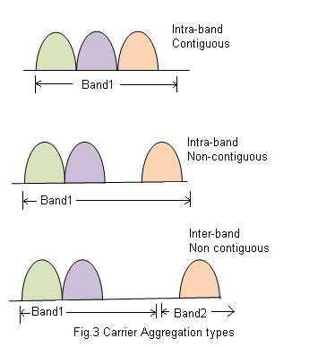
Figure 3: Types of Carrier Aggregation
Figure 3 presents the three main types of carrier aggregation, categorized by how the CCs are allocated from the frequency pool to the UE:
- Intra-band Contiguous: CCs are allocated within the same frequency band and are adjacent to each other.
- Intra-band Non-contiguous: CCs are allocated within the same frequency band, but there is a gap between them.
- Inter-band Non-contiguous: CCs are allocated from different frequency bands.
The spacing between two CCs is calculated as 300KHz * N, where N is any integer.
LTE Carrier Aggregation Frequency Bands
The following lists LTE carrier aggregation frequency bands for intra-band and inter-band configurations in both TDD and FDD modes.
- Intra-band contiguous CA:
- CA_40 (2300 to 2400MHz in UL), (2300 to 2400M in DL), TDD
- CA_1 (1920 to 1980M in UL) ,(2110 to 2170M in DL), FDD
- Inter Band Non Contiguous(FDD)
- CA_1, 1920-1980MHz(UL),2110-2170(DL)
- CA_3, 1710-1785M(UL),1805-1880(DL)
- CA_4, 1710-1755(UL), 2110-2155M(DL)
- CA_5, 824-849(UL), 869-894 (DL)
- CA_7, 2500-2570(UL), 2620-2690(DL)
- CA_13, 777-787(UL), 746-756(DL)
- CA_17, 704-716(UL), 734-746(DL)
References
For more in-depth information about the PHY/MAC layer changes required to support carrier aggregation, please refer to the following links and 3GPP standards:
- https://www.3gpp.org/Carrier-Aggregation-explained
- TR 36.808 carrier aggregation (Base Station)
- TR 36.823 carrier aggregation enhancement (UE)
Advertisement
 RF
RF

