 RF
RF1-Bit and 4-Bit Comparator Design in Verilog
Advertisement
This document provides Verilog HDL code for both 1-bit and 4-bit comparators. Comparators are fundamental digital circuits used to determine the relationship between two input values: whether one is less than, equal to, or greater than the other.
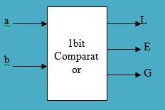
1-Bit Comparator
Symbol
The following is the symbol for a 1-bit comparator.
Truth Table
Here’s the truth table for a 1-bit comparator, detailing the output (L, E, G) based on inputs ‘a’ and ‘b’:
| a | b | L | E | G |
|---|---|---|---|---|
| 0 | 0 | 0 | 1 | 0 |
| 0 | 1 | 1 | 0 | 0 |
| 1 | 0 | 0 | 0 | 1 |
| 1 | 1 | 0 | 1 | 0 |
- L: a < b
- E: a = b
- G: a > b
Verilog Code
module b_comp1 (a, b, L, E, G);
  input a, b;
  output L, E, G;
  wire s1, s2;

  not X1(s1, a);
  not X2(s2, b);
  and X3(L, s1, b);
  and X4(G, s2, a);
  xnor X5(E, a, b);
endmodule
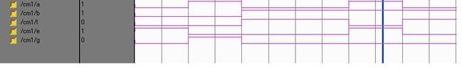
Simulation Result
The simulation results demonstrate the functionality of the 1-bit comparator.
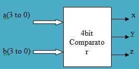
4-Bit Comparator
Below is the symbol representing a 4-bit comparator.
module comp(a, b, aeqb, agtb, altb);
  input [3:0] a, b;
  output aeqb, agtb, altb;
  reg aeqb, agtb, altb;

  always @(a or b)
  begin
    aeqb = 0;
    agtb = 0;
    altb = 0;

    if (a == b)
      aeqb = 1;
    else if (a > b)
      agtb = 1;
    else
      altb = 1;
  end
endmodule
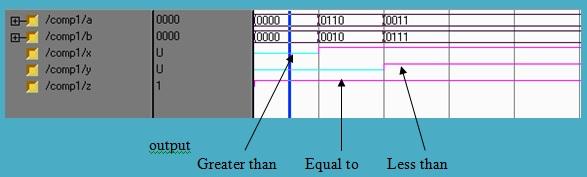
Simulation Result-2
The simulation result confirms the correct operation of the 4-bit comparator.
Advertisement


