 RF
RFRotary Encoder Basics and Types: Understanding Rotary Sensors
Advertisement
This article covers rotary sensor basics and rotary sensor types. The encoder which senses angular position is known as a rotary encoder or sensor. The working of this rotary encoder is also described with the output timing diagrams.
What is a Rotary Sensor or Rotary Encoder?
Introduction: It is a type of position sensor used to determine the angular position of a rotating shaft.
It generates an electrical signal, which is either analog or digital. The electrical output is sensed or used by a micro-controller board or Arduino to perform the desired action.

Figure-1 depicts a Keyes rotary encoder, which provides an indication of the knob position and its direction. It is used for stepper and/or servo motor controls.
Following are the mappings between various pins on the rotary encoder:
- CLK - Encoder Pin-A
- DT - Encoder Pin-B
- SW - NO Pushbutton Switch
- + is connected to 5V Supply
- GND - Encoder Pin-C
Rotary Sensor Types | Rotary Encoder Types
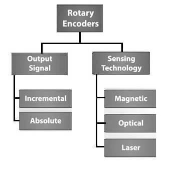
- The rotary encoder or sensor is classified according to the output signal or sensing technology.
- Based on the output signal, rotary sensors are of two types: incremental and absolute. An incremental type of encoder is also known as a quadrature encoder or relative rotary encoder.
- Based on sensing technology, rotary sensors are of three types: magnetic, optical, and laser.
Rotary Sensor Working

The following section describes the working of a rotary sensor:
-
Figure-1 depicts a circular disk with evenly spaced contact zones, which are connected to a common pin “C”. There are two contact pins designated as “Output-A” and “Output-B”.
-
When the disc rotates, pins A and B come into contact with the evenly spaced contact zones, and two square wave output pulses are generated.
-
Either output-A or output-B is used to determine angular or rotational position.
-
But to determine direction, both the output signals and their signal transitions i.e. high to low (H-L) and low to high (L-H) are monitored or measured. As shown for clockwise movement of the shaft, output-A leads output-B in both H-L and L-H transitions.
-
Similarly, anti-clockwise rotational movement can also be measured or tracked.
Advertisement


