Arduino GPS Sensor Interfacing: Guide and Code
Advertisement
This document explains how to interface an Arduino with a GPS sensor, including a diagram, explanation of the sensor’s workings, and example Arduino code.
Introduction to GPS
GPS stands for Global Positioning System. It comprises three segments:
- Space Segment: Satellites orbiting approximately 12,500 miles above the Earth, completing two orbits every 24 hours.
- User Segment: GPS signal receiving devices (like the sensor we’ll be using).
- Control Segment: Command, control, and monitoring stations.
About the GPS Sensor
GPS satellites transmit on multiple frequencies. The L1 frequency (1575.42 MHz) is used for civilian applications, while L2 (1227.6 MHz) is typically for military use.
A GPS sensor generally includes a chip with a rectangular antenna. This chip processes GPS satellite signals to determine its position (latitude and longitude). The sensor requires a DC power supply. It begins outputting data as soon as it identifies satellites within its range, using the NMEA protocol (plain ASCII). The transmission rate is commonly 4800 or 9600 bps, using 8 data bits, no parity, and 1 stop bit. Data is organized into “sentences” of about 80 characters each.
Key specifications to consider when choosing a GPS sensor:
- Sensitivity (dBm): Indicates the receiver’s ability to detect weak signals.
- Time to First Fix (TTFF): The time required for the GPS receiver to acquire satellite signals, navigation data, and calculate a position solution.
- Number of Channels: How many satellites the GPS receiver chip can sense.
- Form Factor: The physical size and shape of the chip.
- Power Consumption (mW): How much power the chip uses.
- Update Rate: The number of position measurements per second.
- Output Type: The format of the data output by the sensor (e.g., serial).
- Supply Voltage: The voltage required to power the sensor.
- Current Consumption: The amount of current the sensor draws.
About the Arduino Board

- The Arduino Uno utilizes the ATmega328 microcontroller from ATMEL, featuring 32 KB of flash memory, 2 KB of RAM, an 8-bit CPU, and 1 KB of EEPROM.
- It offers six analog pins for voltage readings (converting analog to digital).
- Digital pins (0-13) can function as either inputs or outputs.
- It provides interfaces like I2C, digital pins, analog pins, serial communication, and USB.
- Additional features include a reset pin, power port, crystal oscillator, and Tx/Rx LEDs.
- This open-source board is programmed using the Arduino IDE and a USB connection to a computer. The IDE uses a simplified C++ language.
- The board requires a 5V DC power supply, which can be provided by an AC/DC adapter or battery.
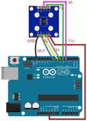
Arduino Interfacing with GPS Sensor: Diagram and Working
The following diagram illustrates how to interface an Arduino with a GPS sensor (GY-GPS6MV2 model).

Arduino GPS Sensor Interface Code
The code below reads GPS data from the sensor and outputs it to the Arduino IDE’s “Serial Monitor” window. To open the Serial Monitor, go to “Tools” -> “Serial Monitor.” You can modify this code to upload the data to a cloud server for further analysis.
#include <SoftwareSerial.h>

static const int RXPin = 4, TXPin = 3;
static const uint32_t GPSBaud = 9600;

// The serial connection to the GPS device
SoftwareSerial ss(RXPin, TXPin);

void setup() {
  Serial.begin(115200);
  ss.begin(GPSBaud);
}

void loop() {
  // Output raw GPS data to the serial monitor
  while (ss.available() > 0) {
    Serial.write(ss.read());
  }
}
Conclusion
This document has detailed the process of interfacing a GPS sensor with an Arduino Uno board. Arduino boards are versatile and can be used with various sensors for diverse applications, including sound sensors, heartbeat sensors, gyro sensors, LDR sensors, color sensors, and pH sensors.
Advertisement
 RF
RF


