 RF
RFGSM Protocol Stack and Architecture Explained
Advertisement
This page covers the GSM protocol stack and GSM protocol architecture for MS (Mobile Station) and BTS (Base Transceiver Station). It describes the architecture of GSM protocol layers, specifically layer 1 (PHY) and layer 2 (LAPD, LAPDm).
Introduction
Let’s understand the GSM Layer 1, Layer 2, and Layer 3 modules of MS (Mobile Station), BTS (Base Transceiver Station), BSC (Base Station Controller), and MSC (Mobile Switching Center). To gain in-depth knowledge, one needs to understand all the message formats of all the modules, such as radio, LAPD, LAPDm, RRM, MM, CM, BTSM, BSSMAP, SCCP, and MTP as described in 3GPP release documents.
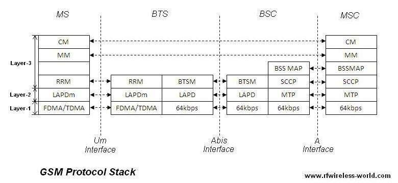
The figure describes the GSM protocol stack at the GSM network elements.
GSM Protocol Layer 1 (Physical Layer)
As mentioned in the figure, FDMA/TDMA is used on the air interface (radio), also called the Um interface.
At the MS, FDMA/TDMA is used, and this format is also followed at the BTS. The BTS takes this format from the MS and converts it to a 64kbps digital format for the digital link and interfaces with the BSC. The BSC communicates with the MSC in the same format.
GSM Protocol Layer 2 (LAPD, LAPDm)
GSM protocol Layer 2 is the data link layer, which performs the following three main functions:
- Establish, maintain, and tear down the link
- Flow control
- Error detection
- Work on the Layer 3 frames
At Layer 2, LAPD and LAPDm are used. LAPD is the ISDN (Integrated Services Digital Network) protocol for the D Channel. LAPDm is a modified version of LAPD for the mobile station. LAPDm does not have CRC for error detection.
This layer uses any of the following formats to carry frames:
- Format A for DCCHs (for channels having no information field)
- Format B for DCCHs (containing an information field)
- Format Bbis for BCCH, PCH, and AGCH.
- Format C for random access signals
The maximum LAPDm frame length is 23 bytes (i.e., 184 bits). Depending on the type of frame format, LAPDm will have an Address field (8 bits), Control field (8 bits), Frame Length (8 bits), signaling data (23 octets), and fill-in data.
The Address field carries two important parameters: C/R and SAPI. C/R indicates whether the frame is a command or response and also specifies the direction of the frame (BS to MS or MS to BS).
SAPI can take a value of 0, 3, or other values. A SAPI of 0 is used for messages from the RRM, MM, and CC, while a SAPI of 3 is used for messages from the SMS and Supplementary Services (SS) messages. The Control field of Layer 2 contains sequence numbers and a type field to differentiate various frames.
There are three types of frames supported here: supervisory, unnumbered information transfer and control function (unacknowledged mode), and numbered information transfer (multiframe acknowledged mode).
The Frame Length field contains the length of the Layer 3 message within the information field of the LAPDm frame. If the message is less than the length specified in parameter N201 (the standard specifies this) of the radio interface, fill-in data octets are used to fill the remaining gap. The value of fill-in data is specified in the GSM TS document.
LAPD at the BTS converts the potentially unreliable physical link of the MS into a reliable link. This connects with the BSC’s MTP part. This is done with the use of CRC and ARQ techniques. ARQ stands for Automatic Repeat Request. ARQ works on the principle of re-transmission of a packet when an erroneous packet is received at the receiver.
The GSM protocol stack can be explored by studying the GSM protocol layers at various network elements, including MS, BTS, BSC, and MSC.
Advertisement


