GSM Downlink Packet Switched (PS) Call Flow Explained
Advertisement
This tutorial explains the Packet Switched (PS) call flow between a Mobile device (UE) and the network for downlink data transfer (downloading data). It details the messages exchanged during GPRS attach and PDP context activation procedures between the mobile and SGSN/VLR/HLR/GGSN.
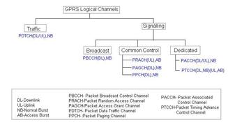
It also covers the channels (PPCH, PRACH, AGCH, PDCH) used at Layer 1 to carry various messages over the air. This article assumes that initial frequency and time synchronization have already been established between the UE and the network, as described in the GSM tutorial.

As shown in the figure, a Packet Paging Request (carried by PPCH/PCH) is sent by the network to alert the mobile device of an incoming packet call. The mobile (UE) then sends a RACH (Random Access Channel) to the network (BTS), and the network assigns a slot (single or multiple) for packet transfer.
GPRS attach procedures are completed by the mobile station for location update and to complete security checks.
In GPRS, a mobile can be in one of three states:
- Idle: The mobile is switched on but not actively using GPRS services.
- Ready: The mobile is attached to the network and ready to send or receive data.
- Standby: The mobile is attached to the network but is temporarily inactive due to a lack of data transfer.
When a mobile is switched on, it starts in the Idle state. After the GPRS attach procedure, it transitions to the Ready state and initiates PDP context activation procedures.
When there are no PDUs (Protocol Data Units) to be transmitted or received, and when a certain timer expires, the mobile enters the Standby state. It remains in this state until there’s PDU activity.
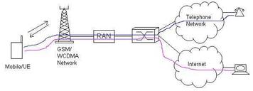
To enable internet connectivity, an IP address needs to be assigned to the mobile, and connectivity with the APN (Access Point Name) needs to be established. This is achieved through PDP context activation procedures.
The PDP context provides routing information and QoS (Quality of Service) parameters supported by the GSM/GPRS network.
The Mobile Station (MS) specifies the network SAP (Service Access Point) and the APN of the PDN (Packet Data Network) to establish a connection.
All messages are routed to the SGSN/GGSN/PDN via the BTS (Base Transceiver Station). A tunnel is established between the SGSN and GGSN for the communication of protocol messages.
As defined in the GSM protocol stack, messages flow between the mobile and the network at various layers (Layer 3, Layer 2, and Layer 1 - the physical layer).
The message flow in the diagram is self-explanatory and demonstrates how a Packet Switched downlink data call is established in GSM.
Advertisement
 RF
RF


