5G NR PDCP Layer: Functions, Architecture, and Procedures
Advertisement
This page provides an overview of the 5G NR PDCP layer, including its functions, architecture, procedures for data transfer during transmit/receive operations, and the formats of its Data and Control PDUs.
Introduction
- PDCP stands for Packet Data Convergence Protocol. The 3GPP specification TS 38.323 defines the PDCP protocol.
- As shown in the figure below, it lies between the RLC layer on the lower side and the RRC layer on the higher side of the control protocol stack.
- In the data user plane, it resides at the top of the stack.

Figure 1: 5G NR Protocol Stack Layers
The figure above depicts the 5G NR protocol stack, highlighting the position of the PDCP layer. As illustrated, the PDCP layer provides services to the upper layers (RRC or SDAP) and relies on services from the RLC, MAC, and PHY layers.

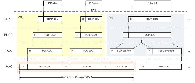
Figure 2: Data Flow Through 5G NR protocol layers
The figure above shows the data flow through various protocol layers in the 5G NR stack.
PDCP provides the following services to the upper layers:
- Transfer of user plane data and control plane data
- Header compression/decompression using ROHC
- Ciphering/Deciphering
- Integrity protection
PDCP expects the following services from the lower layers:
- Acknowledged data transfer service
- Unacknowledged data transfer service
5G NR PDCP Layer Functions
The functions of the PDCP layer are as follows:
- Transfer of data (user plane or control plane)
- Maintenance of PDCP SNs (Sequence Numbers)
- Header compression and decompression using the ROHC protocol
- Ciphering and deciphering
- Integrity protection and integrity verification
- Timer-based SDU discard
- For split bearers, routing is performed
- Activation/Deactivation of PDCP duplication
- Reordering and in-order delivery
- Out-of-order delivery
- Duplicate discarding
PDCP Architecture (Structure, Entities)

Figure 3: PDCP architecture structure view
- The architecture is based on a radio interface protocol.
- The PDCP sublayer is configured by RRC.
- It is used for RBs (Radio Bearers) mapped onto logical channels, including DCCH and DTCH.
- Each RB is associated with one PDCP entity. Each PDCP entity is associated with 1, 2, or 4 RLC entities, depending on the RB characteristics or RLC modes. RB characteristics are uni-directional / bi-directional or split/non-split.
- For non-split bearers, each PDCP entity is associated with 1 UM RLC entity/2 UM RLC entities/1 AM RLC entity.
- For split bearers, each PDCP entity is associated with 2 UM RLC entities/4 UM RLC entities/2 AM RLC entities (same direction).
PDCP Entity
- The PDCP entities are located in the PDCP sublayer. Several PDCP entities may be defined for a UE. Each PDCP entity carries the data of one radio bearer.
- A PDCP entity is associated with either the control plane or the user plane, depending on which radio bearer it is carrying data for.

Figure 4: PDCP architecture functional view
- The figure above depicts a functional view of the PDCP entity used for the PDCP sublayer.
- The data can be either uncompressed PDCP SDU or compressed PDCP SDU. Uncompressed data is associated with the user plane or control plane. Compressed data is associated with the user plane only.
- Depending on the Plane, the PDU can be of two types: control PDU or data PDU.
- Control PDU types include either a PDCP status report or interspersed ROHC feedback.
PDCP Procedures for Data Transfer
- There are three main PDCP entity handling procedures: PDCP entity establishment, re-establishment, and release.
- After establishment, PDCP procedures are associated with either transmitting or receiving operations.
- During the transmit operation, the PDCP entity receives an SDU from the upper layer. Various operations are performed on this received SDU before it is passed to the lower layers and, subsequently, to the radio interface (Uu).
- When the UE transmits, the NG-RAN receives, and when the NG-RAN transmits, the UE receives.
- Similar functionalities are performed when a data PDU is received from lower layers.
- The PDCP SDU size and the PDCP control PDU size are both 9000 bytes (maximum).
- The length of the PDCP SN is either 12 bits or 18 bits, configured by upper layers.
PDCP Layer Data PDU and Control PDU Formats
- A PDCP PDU is a bit string that is byte aligned (i.e., a multiple of 8 bits) in length.
- PDCP SDUs are bit strings that are byte aligned (i.e., a multiple of 8 bits) in length.
- A compressed or uncompressed SDU is included in a PDCP Data PDU from the first bit onward.
The following figure depicts the PDCP Data PDU format with a 12-bit PDCP SN. This format is applicable for SRBs.

Figure 5: PDCP Data PDU SRBs format
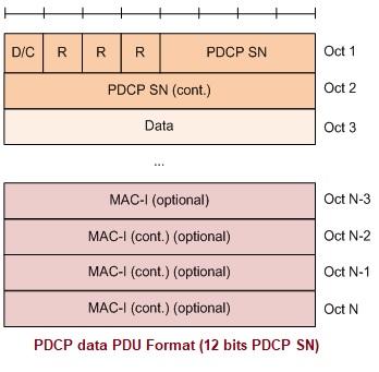
The following figure depicts the PDCP Data PDU format with a 12-bit PDCP SN. This format is applicable for UM DRBs and AM DRBs.

Figure 6: PDCP Data PDU Format 12-bits SN
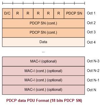
The following figure depicts the PDCP Data PDU format with an 18-bit PDCP SN. This format is applicable for UM DRBs and AM DRBs.

Figure 7: PDCP Data PDU Format 18-bits SN
The following figure depicts the PDCP Control PDU format which carries one PDCP status report. This format is applicable for AM DRBs.

Figure 8: PDCP Control PDU format
The PDCP Control PDU format carrying one interspersed ROHC feedback is applicable for UM DRBs and AM DRBs.
References
- 3GPP TS 38.323, Packet Data Convergence Protocol (PDCP) specification (Release 15)
Advertisement
 RF
RF


