5G NR MAC Layer: Architecture, Channels, Procedures, and Header
Advertisement
This article provides an overview of the 5G NR MAC layer, covering its functions, architecture, channel mapping, procedures, and the format of its header and subheaders.
Introduction to 5G NR
5G NR (New Radio) is the latest cellular wireless technology, designed to deliver data rates ten times faster than its predecessor, LTE. It adheres to 3GPP specifications from Release 15 onwards. Key features of 5G NR include:
- Operation on two frequency bands: sub-6 GHz and millimeter wave (above 20 GHz).
- Support for massive MIMO with 64 to 256 antennas.
- Offering 10 Gbps within 100 meters using a 100MHz bandwidth.

Figure 1: 5G NR Protocol Stack Layers
As shown in Figure 1, the MAC layer sits within the 5G NR protocol stack. The MAC layer provides services to upper layers and receives services from the physical layer. The physical layer provides transport channels to the MAC layer to facilitate data transfer over the radio interface.
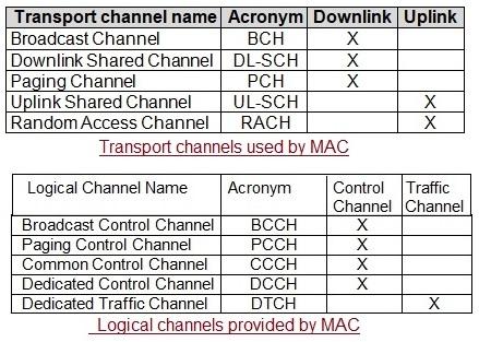
The MAC layer, in turn, offers logical channels to the RLC sublayer. Logical channels exist between the MAC and RLC layers, while transport channels exist between the PHY and MAC layers. Therefore, the MAC layer acts as an interface between logical channels and physical layer transport channels.

Figure 2: Data Flow Through 5G NR Protocol Layers
Figure 2 illustrates the flow of data through the various protocol layers of the 5G NR stack.
5G NR MAC Layer Architecture and Functions

Figure 3(a): 5G NR MAC structure overview, MCG

Figure 3(b): 5G NR MAC structure overview, SCG
Figures 3(a) and 3(b) depict the 5G NR MAC layer architecture for MCG (Master Cell Group) and SCG (Secondary Cell Group), respectively.
The physical layer provides the following services to the MAC sublayer:
- Data Transfer
- HARQ feedback signaling
- Scheduling Request signaling
- CQI (Channel Quality Indication) measurements
The MAC sublayer provides two main services to upper layers: data transfer and radio resource allocation. Other functions of the 5G NR MAC include:
- Mapping between logical and transport channels (both Downlink and Uplink).
- Multiplexing of MAC SDUs onto TBs (Transport Blocks) in the Uplink. SDUs belong to logical channels, and transport blocks belong to transport channels.
- Demultiplexing of MAC SDUs from TBs in the Downlink.
- Scheduling information reporting in the Uplink.
- Error correction through HARQ in the Downlink and Uplink.
- Logical Channel Prioritization in the Uplink.
5G NR MAC Channel Mapping

Figure 4: 5G NR logical channels and transport channels
Figure 4 depicts the MAC logical channels and PHY layer transport channels used in 5G NR technology. These channels have specific functions in the downlink or uplink. PDSCH, PBCH, and PDCCH are used in the downlink, while PUSCH, PUCCH, and RACH are used in the uplink. The reference signals in the downlink are DMRS, PT-RS, CSI-RS, PSS, and SSS. The reference signals in the uplink are DMRS, PTRS, and SRS.

Figure 5: 5G NR logical channel to transport channel mapping
Figure 5 illustrates the mapping of logical channels to transport channels and vice versa within 5G NR.
5G NR MAC Procedures
The following table outlines various 5G NR MAC procedures and their respective functionalities within the MAC layer:
| 5G NR MAC Procedures | Description |
|---|---|
| Random Access Procedure | Obtains the initial uplink grant for the UE and aids in synchronization with the gNB (i.e., network). It encompasses Random Access procedure initialization, Random Access Resource selection, Random Access Preamble transmission, Random Access Response reception, Contention Resolution, and Completion of the Random Access procedure. |
| DL-SCH data transfer | Performs all necessary steps for downlink data transfer. |
| UL-SCH data transfer | Performs all necessary steps for uplink data transfer. |
| Scheduling request (SR) | Used by the UE to transmit a request to the gNB (i.e., network) to obtain a UL grant. |
| PCH reception | Facilitates monitoring of paging messages during specific time periods. |
| BCH reception | Carries basic information regarding the 5G NR cell (e.g., MIB, SFN, etc.). |
| DRX (Discontinuous Reception) | Aids in monitoring PDCCH according to a specific pattern in a discontinuous manner, thereby reducing energy consumption. |
| Other procedures | Includes transmission and reception without dynamic scheduling, activation/deactivation of SCells, activation/deactivation of PDCP duplication, BWP (Bandwidth Part) operation, handling of measurement gaps, handling of MAC CEs, beam failure detection, and recovery operation, etc. |
5G NR MAC Header and Subheaders
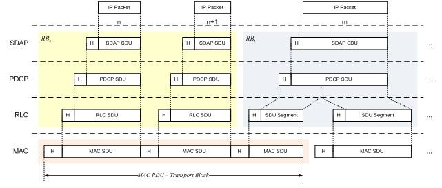
A MAC PDU consists of one or more MAC sub-PDUs. Each MAC sub-PDU contains one of the following:
- A MAC subheader only (including padding)
- A MAC subheader and a MAC SDU
- A MAC subheader and a MAC CE (Control Element)
- A MAC subheader and padding
The MAC SDUs are of variable sizes, and each MAC subheader corresponds to either a MAC SDU, a MAC CE, or padding.

Figure 6: 5G NR MAC PDU examples-Downlink (DL) and Uplink (UL)
Figure 6 shows examples of 5G NR MAC PDUs for downlink (DL) and uplink (UL).

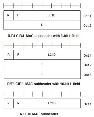
Figure 7: 5G NR MAC subheader types
Figure 7 depicts the MAC subheader types. Let’s explore the header and subheader fields and their meanings in the 5G system.
The MAC subheader consists of fields such as LCID, “L”, “F”, and “R”.
-
LCID field: LCID stands for Logical Channel ID. It identifies the logical channel instance of the corresponding MAC SDU or the type of the corresponding MAC CE or padding. There is only one LCID field for each MAC subheader, and it is 6 bits in size. The values of LCID for DL-SCH and UL-SCH are detailed in the tables below.
-
L-Field: “L” indicates the length field of the corresponding MAC SDU or variable-sized MAC CE in units of bytes. One “L-field” exists for one MAC subheader. More “L-fields” exist for subheaders corresponding to fixed-sized MAC CEs and padding. The “L-field” size is indicated by the F-field.
-
F-field: Refers to the length field size. It is one bit in size. There is one F-field per MAC subheader, except for subheaders corresponding to fixed-sized MAC CEs and padding. A value of 0 in the F-field refers to 8 bits of the Length field, while a value of 1 refers to 16 bits.
-
R: Reserved bit, set to zero.

Figure 8: LCID Table for DL-SCH
Figure 8 shows LCID values for the DL-SCH channel, while Figure 9 shows LCID values for the UL-SCH channel.

Figure 9: LCID Table for UL-SCH
References
- 3GPP TS 38.321 V15.2.0 (2018-06), Medium Access Control (MAC) protocol specification (Release 15)
- 3GPP TS 38.300 V15.2.0 (2018-06), NR; NR and NG-RAN Overall Description; Stage 2 (Release 15)
Advertisement
 RF
RF


