RF
RFTMOD and TCON Registers in 8051 Microcontroller
Advertisement
The Timer Mode (TMOD) and Timer Control (TCON) registers are essential for configuring and controlling the timers in the 8051 microcontroller. Let’s dive into their functions and structure.
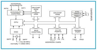
The 8051 microcontroller has two 16-bit timers/counters: Timer 0 and Timer 1. The TMOD and TCON registers are used to set up and manage these timers/counters. They can be configured as either timers or event counters.
When acting as timers, the register increments with each machine cycle. Essentially, the timer functions as a counter, counting machine cycles. One machine cycle consists of approximately 12 oscillator periods. Therefore, the count rate is about 1/12th of the oscillator frequency.
When configured as counters, the register increments in response to a 1-0 transition on its corresponding external input pin. The external input is sampled during S5-P2 of each machine cycle.
Format of the TMOD Register
The TMOD register sets the mode of operation for Timer 0 and Timer 1. It’s an 8-bit register; the lower nibble (bits 0-3) controls Timer 0, and the upper nibble (bits 4-7) controls Timer 1. Each nibble is further divided into mode control bits and gate control bits. TMOD is not bit addressable.

- GATE: When
GATE=1andTRx(in TCON) is set, Timer/Counter-x will run while the INT-x pin is high (Hardware Control). WhenGATE=0, Timer/Counter-x will run only whenTRx=1(software control). - C/T (with a bar above the T): Set to 0 for timer operation and 1 for counter operation.
- M1, M0: Mode Selector bits.
| M1 | M0 | Operating Mode |
|---|---|---|
| 0 | 0 | 13-bit timer |
| 0 | 1 | 16-bit timer/counter |
| 1 | 0 | 8-bit auto-reload timer/counter |
| 1 | 1 | TL0 is an 8-bit timer/counter controlled by standard timer 0 control bits. TH0 is an 8-bit timer controlled by timer 1 control bits. |
Bit Structure of the TCON Register
The TCON register controls the timers and external interrupts. It’s also an 8-bit register with specific bits allocated to Timer 0, Timer 1, and the external interrupts. TCON is bit addressable.

- TF1 (TCON.7): Timer 1 overflow flag
- TR1 (TCON.6): Timer 1 run control bit
- TF0 (TCON.5): Timer 0 overflow flag
- TR0 (TCON.4): Timer 0 run control bit
- IE1 (TCON.3): External interrupt 1 edge flag
- IT1 (TCON.2): Interrupt 1 type control bit
- IE0 (TCON.1): External interrupt 0 edge flag
- IT0 (TCON.0): Interrupt 0 type control bit
Summary
- TMOD Register: Configures the mode (operation mode, counter/timer selection, and gate control) for Timer 0 and Timer 1.
- TCON Register: Controls the start/stop of the timers, detects external interrupts, and holds the overflow flags for the timers.
Understanding these registers is crucial for effectively programming the 8051’s timers and handling interrupts.