 RF
RF8051 Microcontroller: Understanding IE and IP Registers
Advertisement
In the 8051 microcontroller, the Interrupt Enable (IE) and Interrupt Priority (IP) registers are used to manage and prioritize interrupts. Let’s explore these registers in detail.
The Intel 8051 microcontroller supports five interrupt sources: two external interrupts, two timer interrupts, and one serial port interrupt. The external interrupts INT0 and INT1 can be either level-triggered or edge-triggered, depending on the settings of bits IT0 and IT1 in the TCON register. The flags that generate these interrupts are IE0 and IE1.
When an external interrupt is generated, the flag that generated the interrupt is cleared by the hardware when the service routine is vectored to the Interrupt Service Routine (ISR) location. This only happens if the interrupt was edge-triggered. If the interrupt was level-triggered, the external requesting source controls the requested flag, rather than the on-chip hardware.
Timer-0 and Timer-1 interrupts are generated by registers TF0 and TF1. When a timer interrupt is generated, the flag that generated the interrupt is cleared by the on-chip hardware when the program enters the interrupt service routine.
The serial port interrupt is generated by the logical-OR of registers RI/TI. These flags are not cleared by hardware when the service routine is vectored. The service routine needs to determine whether RI or TI generated the interrupt.
IE and IP are the registers used to enable and set the priority of the interrupt system in the microcontroller.
Structure of the IP Register in the 8051
The IP register is an 8-bit register used to set the priority levels for each interrupt. Higher priority interrupts can interrupt lower priority ones. IP is bit-addressable. Here’s the bit structure of the IP register:
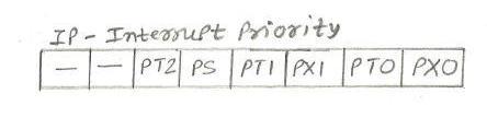
- PS (IP.4): Serial Port Interrupt Priority bit
- PT1 (IP.3): Timer 1 Interrupt Priority bit
- PX1 (IP.2): External Interrupt 1 Priority bit
- PT0 (IP.1): Timer 0 Interrupt Priority bit
- PX0 (IP.0): External Interrupt 0 Priority bit
Format of the IE Register in the 8051
The IE register is an 8-bit register that enables or disables interrupts globally and individually for each interrupt source. IE is bit-addressable. Here’s the bit structure of the IE register:
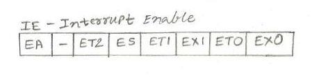
- EA (IE.7): Global Interrupt Enable bit. If EA=0, no interrupt will be enabled, and interrupt will be disabled globally.
- IE.6: Reserved
- IE.5: Reserved
- ES (IE.4): Serial Port Interrupt Enable bit
- ET1 (IE.3): Timer 1 Overflow Interrupt Enable bit
- EX1 (IE.2): External Interrupt 1 Enable bit
- ET0 (IE.1): Timer 0 Overflow Interrupt Enable bit
- EX0 (IE.0): External Interrupt 0 Enable bit
Summary
-
IE Register: Used to enable or disable interrupts globally and individually for each interrupt source. The bits control the enabling of interrupts for Timer 0, Timer 1, Serial Port, External 0, and External 1.
-
IP Register: Used to set the priority levels of interrupts. Higher priority interrupts (with bit set to 1) can interrupt lower priority ones (with bit set to ‘0’).
Understanding and correctly configuring these registers is crucial for efficient interrupt management in the 8051 microcontroller.
Advertisement


