 RF
RFRF Mixer: Function, Equation, Types & Applications
Advertisement
An RF mixer is a vital component in communication systems, enabling frequency conversion and signal modulation. It operates based on the principle of mixing two signals to produce new frequencies. In this guide, we’ll explain the functions of an RF mixer, its key equations, types, and applications across various industries.
A radio-frequency (RF) mixer is an essential component in microwave and RF circuits, particularly in communication systems, radar, and other wireless applications. Its primary function is to combine two or more input signals at different frequencies and produce an output signal that contains the sum and difference frequencies of the inputs. This process is known as frequency mixing.
The primary function of an RF mixer can be summarized as follows:
- Frequency Conversion: The mixer is used to convert input signals from one frequency to another. This is crucial in various applications, such as frequency translation in communication systems.
- Signal Processing: The mixer can be employed for modulation and demodulation of signals, allowing the transmission and reception of information in a more manageable frequency range.
RF Mixer Technical Specifications
When selecting an RF mixer, the following specifications need consideration:
- Frequency ranges: The RF, LO, and IF ranges for which the mixer is designed.
- Dynamic range: Input power range over which the mixer is useful.
- LO power level: The design or maximum LO power.
- Conversion loss: The ratio of IF to RF power.
- 1-dB input compression level: The RF power at which the conversion loss increases by 1 dB.
- IM intercept points: Usually the IIP3 (Third-order Intercept Point).
- Isolation: Between the various ports, LO, RF, and IF; for example, how much is the LO power attenuated in getting to the IF/RF ports.
- VSWR: At all three ports: RF, IF, and LO.
RF Mixer Equation and Working
An RF mixer’s behavior is described by the following equation:
Where:
- represents all output signals.
- and are the two input signals.
- and are the order of the harmonics, from zero (fundamental) to infinity.
Usually, in all mixers, second-order products and will have the highest amplitudes (, (actually: )). and are also second-order outputs.
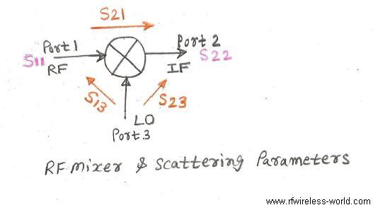
An RF mixer is a three-port device. The three ports are usually denoted as radio frequency (RF), intermediate frequency (IF), and local oscillator (LO). The RF and IF ports are bidirectional. Since a mixer has three ports, this means it has nine S-parameters. Typically only five of these are tested in practice, as shown in the figure above.
RF Mixer Types
RF mixers usually consist of a single diode or multiple diodes, or some other electronic device, e.g., a FET (Field Effect Transistor). There are different types of mixers: single-ended, balanced (90 degree), balanced (180 degree), double-balanced, and image reject mixers. Practically, mixers are often of the balanced type, in which even-order harmonics will not be produced at the output due to the design.
There are various types of RF mixers, and they can be broadly categorized into three main types:
- Additive Mixers: Produce the sum of the input frequencies.
- Subtractive Mixers: Generate the difference frequency between the input signals.
- Multiplicative Mixers: Produce both the sum and difference frequencies.
Hence one can find the sum and difference of input frequences and . and will not be produced. If there are no other outputs, if components are ideal (lossless) then the mixer circuit behaves as per equation below.
where and are the time domain representations of and input frequencies. The 1 by 2 factors indicates input amplitude is divided between two outputs. 1 by 2 factor represents 6 dB conversion loss of the mixer.
RF Mixer Circuit Design
RF mixers with a high third-order intercept point and higher LO/RF and LO/IF isolation are usually considered for RF circuit design. These mixers provide the best performance in mixer-based RF systems.
The specific circuit configuration of an RF mixer depends on its type and application. However, some common mixer circuit configurations include:
- Single-Balance Mixers: Use a single diode or transistor to achieve mixing.
- Double-Balance Mixers: Utilize two diodes or transistors in a balanced configuration to suppress unwanted harmonics and improve performance.
Following thumb rules are useful during RF Mixer circuit design.
- LO power should be at least 20dB higher than RF Power.
- 1dB compression point is 5 to 10 dB lower than LO Power.
- Usually pads have been used at all the three ports of RF mixer. But When matching and intermodulation products are a problem use isolators in the place of pads.
Refer to our page on the design of RF frequency converters to know the use of RF mixers in microstrip-based designs. Refer to RF mixer circuit designs for Balanced mixers and FET & Image reject mixers.
RF Mixer Applications
RF mixers find applications in various fields, including:
- Communication Systems: Used for frequency upconversion and downconversion in transmitters and receivers.
- Radar Systems: Employed for frequency translation and signal processing.
- Test and Measurement Equipment: Utilized in spectrum analyzers and signal generators.
- Satellite Communication Systems: Used for frequency translation in uplink and downlink paths.
- Medical Imaging Systems: Applied in microwave imaging and sensing.
Conclusion
RF mixers are indispensable in modern communication systems, offering efficient frequency management and signal processing capabilities. Understanding their operation and applications enhances the design of RF systems.
Advertisement


