
Freewheeling Diode: Definition, Function, and Working Principle
Advertisement
A freewheeling diode, also known as a flyback diode or a commutating diode, is a crucial component in electronic circuits. Its primary purpose is to provide a safe path for current when an inductive load is de-energized. Essentially, it prevents damaging voltage spikes and protects other components within the circuit, especially when dealing with inductive loads such as relays, solenoids, or electric motors.
Function
When current flows through an inductive load (like the coil in a relay or a motor), energy gets stored in the magnetic field created. Now, when the power to that load is suddenly cut off (de-energized), the magnetic field collapses rapidly. This collapse induces a significant voltage spike in the reverse direction. This spike can be high enough to damage sensitive components in the circuit.
The freewheeling diode steps in to prevent this damage. It provides an alternate path for the current to circulate in a loop. This allows the energy stored within the inductor to dissipate gradually, effectively preventing that potentially harmful voltage spike.
Freewheeling Diode Circuit and Symbol
The symbol for a freewheeling diode looks much like a standard diode symbol. However, it’s often marked with a small arrow to indicate the direction of current flow when the diode is conducting.
The freewheeling diode is always connected in parallel with the inductive load. Its cathode (the end with the bar) is connected to the positive side of the load, and its anode (the other end) is connected to the negative side.
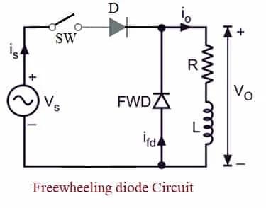
In this setup, when the switch opens and the inductive load is de-energized, the freewheeling diode kicks in. It provides a path for the current to continue flowing, protecting the rest of the circuit from those dangerous voltage spikes.
Important Note: The diode you choose for this application needs to have a sufficient current and voltage rating to handle the demands of the inductive load. Make sure it can handle the expected current and voltage characteristics.
Working Principle
Let’s break down how a freewheeling diode works in a circuit, step by step:
-
Energizing Phase: When the switch (which could be a transistor or a relay) is closed, current flows directly through the inductive load. During this phase, the freewheeling diode is reverse-biased (meaning current can’t flow through it).
-
De-energizing Phase: This is where the diode really shines. When the switch is opened to de-energize the inductive load, the magnetic field starts to collapse. This collapsing field induces a reverse voltage across the inductor.
-
Freewheeling Diode Activation: Because of the induced reverse voltage, the freewheeling diode now becomes forward-biased. This allows it to conduct current. It provides a dedicated path for the inductor’s current to circulate in a loop.
-
Energy Dissipation: The freewheeling diode allows the energy that was stored in the inductor to dissipate gradually. As the current flows through the diode, it prevents the voltage across the load from spiking to potentially harmful levels.
Conclusion
In conclusion, freewheeling diodes are essential components in protecting circuits with inductive loads. They provide crucial protection against voltage spikes, ensuring the longevity and reliability of electronic devices.
Advertisement


