 RF
RFDAC Types: Weighted Resistor vs. R-2R Ladder
Advertisement
This page explores the differences between various Digital-to-Analog Converter (DAC) types, including their block diagrams and defining equations. We will cover the weighted resistor DAC, the R-2R inverting ladder DAC, and the R-2R non-inverting ladder DAC, highlighting their respective advantages and disadvantages.
As the name suggests, a DAC converts digital information into an analog signal (either voltage or current). Common components used in DAC implementations include switches, resistors, and operational amplifiers (op-amps).
Weighted Resistor DAC
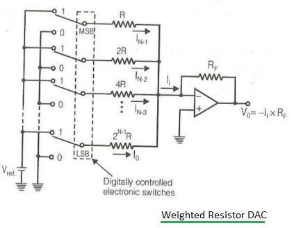
Figure-1: Block diagram of binary weighted resistor DAC.
Figure 1 shows a block diagram of a binary weighted resistor DAC. It utilizes a summing op-amp circuit. Weighted resistors are used to differentiate each bit, from the Most Significant Bit (MSB) to the Least Significant Bit (LSB). Transistors act as switches, connecting either the reference voltage (Vref) or ground, representing a bit’s high or low state.
The output voltage from a binary weighted resistor DAC is calculated as follows:
Vo = { RF /(2N-1 *R)}* {2N-1 *VN-1 + 2N-2 *VN-2 + … + 21 *V1 + 20 *V2 }
Advantages:
- Simple in construction.
- Offers fast conversion speeds.
Disadvantages:
- Requires a large range of resistor values, demanding high precision for low-value resistors.
- Needs low switch resistances in the transistors.
- Can be expensive to manufacture.
Due to these limitations, the resolution of weighted resistor DACs is typically limited to 8-bit.
R-2R Ladder DAC (Non-Inverting)
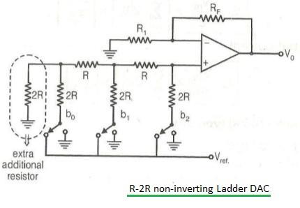
Figure-2: R-2R Ladder DAC of non-inverting type.
Figure 2 illustrates an R-2R Ladder DAC of the non-inverting type, which utilizes a non-inverting operational amplifier.
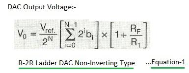
Equation-1: Output analog voltage for R-2R ladder DAC (non-inverting).
Equation 1 (above) represents the formula for the output analog voltage of a non-inverting R-2R ladder DAC.
R-2R Ladder DAC (Inverting)
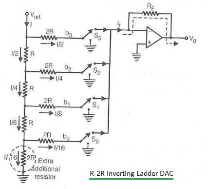
Figure-3: Block diagram of R-2R Ladder DAC of inverting type.
Figure 3 depicts the block diagram of an R-2R Ladder DAC of the inverting type, which employs an inverting operational amplifier.
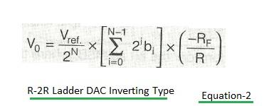
The output voltage for an N-Bit DAC is expressed as follows:
Advantages:
- Only two resistor values are used in R-2R ladder types.
- Does not require the same level of precision resistors as binary weighted DACs.
- Cheaper and easier to manufacture.
Disadvantages:
- Has a slower conversion rate compared to weighted resistor DACs.
DAC Resolution and Step Size
For an N-bit DAC:
- Number of different levels = 2N
- Number of Steps = 2N - 1
Resolution or step size of DAC = Analog output/Number of steps = Va/( 2N - 1 )
% Resolution = (Step Size/Full scale output) x 100 %
Advertisement


