 RF
RFIIP3 vs OIP3: Understanding the Difference
Advertisement
This page explains the difference between IIP3 and OIP3, which stand for Input Third Order Intercept Point and Output Third Order Intercept Point, respectively. The Input Third Order Intercept Point (IIP3) and Output Third Order Intercept Point (OIP3) are critical parameters in assessing the linearity and performance of RF components like amplifiers and mixers.
Introduction
When two or more signals are mixed in a nonlinear component (active or passive), new signals are generated as a result of the product of these original signals. This condition is known as Intermodulation Distortion (IMD).
The frequencies generated due to intermodulation can be the sum or difference of various IMD products. Based on the IMD products, there will be second-order, third-order, fourth-order, and so on.
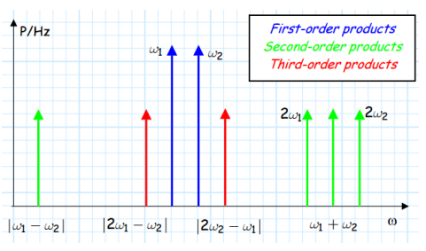
These IMD products are shown in Figure 1 below.
As shown in the figure, there are many IMD products, but the major interference will be due to 2w1 + w2 and 2w1 - w2 as they exist near the desired frequencies (w1, w2) in the frequency spectrum.
The intermodulation distortion is generated in the transmitter when two or more signals are mixed in a nonlinear component of the transmitter, such as an RF mixer, MMIC amplifier, etc.
The table below mentions third-order intermodulation output frequencies due to the application of two input frequency channels (f1 and f2).
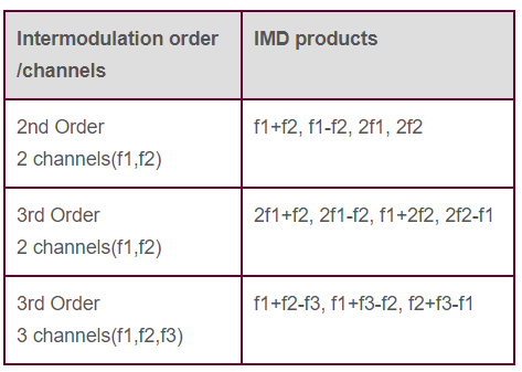
As mentioned above, only third-order products at the output are higher in magnitude and close to the desired frequencies (f1 and f2). Hence, these third-order products cause interference to the desired signal frequencies.
Let’s understand the terms IIP3 and OIP3 associated with the third-order IMD curve (with slope 3).
IIP3 | Input Third Order Intercept Point
IIP3 refers to the hypothetical input power level where the power of third-order intermodulation products would equal the power of the fundamental output signal, indicating the device’s tolerance to high input signals before significant distortion occurs.

Each 1dB increase in input power results in a 3dB increase in output power. Hence, a slope of 3 is achieved, as shown in Figure 2.
The Third Order Intercept (TOI) point is a result of third-order IMD products, specifically 2w1 - w2 as well as 2w2 - w1, as shown in the frequency spectrum of Figure 1. The TOI point is called a figure of merit. It characterizes an RF receiver’s tolerance when subjected to multiple RF signals outside of the desired passband.
Due to third-order IMD products, the RF circuit does not function as desired at the IIP3 input level.
1dB Gain Compression Point (P1dB point)
It’s the output point where a 2dB increase in input power fed to the amplifier (or nonlinear RF circuit) results in a 1dB change in the output power.
The 1dB curve shows IP 1dB and OP 1dB as Input and output 1dB gain compression points. The extrapolated point where IM3 is equal to 0 dBc is known as the third-order intercept point IP3.
The extrapolated point where the curves of the fundamental signal and third-order distortion product signal meet is called the Third Order Intercept Point (IP3).
At this point, the input power level is known as IIP3, and the output power when this situation occurs is known as the OIP3 point.
IIP3, as mentioned above, is the 3rd order intercept point at the input of the amplifier for OIP3 (Output third Order Intercept point).
Figure 2 also shows the IP2 point. This is a result of second-order IMD products (i.e., f1 + f2 and f1 - f2) and second-order harmonic frequencies (2*f1, 2*f2).
The extrapolated point where curves of the fundamental signal and second-order distortion product signal meet is called the second-order intercept point (IP2). The input power level is known as IIP2, and the output power when this occurs is known as the OIP2 point.
OIP3 | Output Third Order Intercept Point
OIP3 denotes the corresponding output power level at this intercept point, reflecting the maximum output power the device can deliver before nonlinearities become prominent.
In other words, the output power of the nonlinear device when fed with input power having a strength equal to the IIP3 level is known as OIP3.
Ideally, OIP3 is usually about 10 dB higher than the P1dB gain compression point (i.e., OP 1dB).

The figure depicts the IP3 measurement setup.
OIP3 = P OUT + ΔP/2
Example:
Let f1 and f2 signals are measured at a power level of -10 dBm (this is P OUT ), and 2f1-f2 and 2f2-f1 are measured at a power level of approximately -40dBm.
ΔP = -10-(-40) = +30 dBc
Now, OIP3 = -10 dBm + 30/2 dB or OIP3 = +5 dBm
If the gain of the device is, say, + 6 dB, then IIP3 = OIP3 - G
Hence, IIP3 = +5 - 6 = -1 dBm
Relation Between IIP3 and OIP3
Let x and y be the input power and output power, respectively. Let A be the transfer function between X and Y. (A is “gain” if the device is an amplifier).
Y = A0 + A1.X 1 + A2.X 2 + A3.X 3 +… + Ai.X i +… An.X n
Where,
- A0 is a constant term which is independent of the value of X.
- A1*X is the linear portion.
- A2.X 2 is the quadratic term, i.e., second order.
- A3.X 3 is the third-order part.
The following equation expresses the relation between IIP3 and OIP3.
Gain dB + IIP3 dBm = OIP3 dBm
Where,
- IIPn is the nth-order input intercept point, measured on the input power axis (i.e., X-axis).
- OIPn is the nth-order output intercept point, measured on the output power axis (i.e., Y-axis).
Conclusion
The relationship between them is defined by the device’s gain: OIP3 equals IIP3 plus the gain. Understanding these metrics is essential for designing and evaluating RF systems to ensure signal integrity and minimize distortion in communication channels.
Advertisement


