 RF
RFBGP vs MPLS: Understanding the Key Differences in VPNs
Advertisement
This page describes BGP vs MPLS protocols and mentions the functional difference between BGP and MPLS protocols used in VPN (Virtual Private Network). BGP stands for Border Gateway Protocol. MPLS stands for Multi Protocol Label Switching.
About Virtual Private Network
It extends a private network over a shared infrastructure. The VPN helps interconnect geographically separate sites with the same privacy and reliability as a secured private network.
There are different types of VPNs:
- Traditional VPNs: Based on Frame Relay (Layer 2) and ATM (Layer 2)
- CPE-based VPNs: Based on L2TP and PPTP (Layer 2) and IPSec (Layer 3)
- Provider Provisioned VPNs (PP-VPNs): Based on MPLS-based Layer 2 VPNs, BGP/MPLS VPNs or RFC2547bis (Layer 3)
We will go through RFC2547bis based BGP/MPLS VPN network components and architecture. We will also go through how BGP/MPLS VPN works with respect to control flow and data flow between two sites.
BGP/MPLS VPN solves the following two common problems:
- There will be a problem with VPNs having a large number of sites.
- Moreover, to add a new site, all the existing sites need to be configured.
BGP/MPLS VPN type solves the scaling issue as well as configuration issue and allows support for thousands of VPNs with hundreds of sites supported per VPN. It also provides support for over-lapping address space. This model does not allow traffic of one VPN to be visible in another VPN.
BGP/MPLS VPN Network Topology and Components
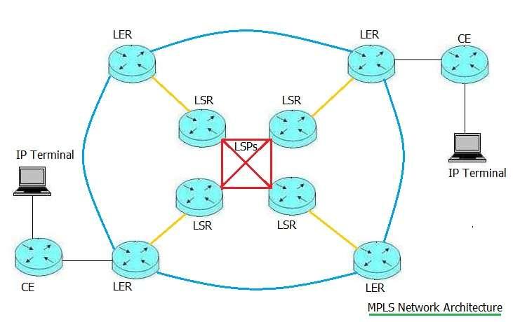
Following are the major BGP/MPLS VPN network components as depicted in the figure-1. The figure is derived for illustration purposes only from Juniper Networks Inc. It includes CE (Customer Edge) router, PE (Provider Edge) router and P (provider) routers.
Following are the useful points with respect to these network components.
- CE router interfaces with PE router, but not interfaced with other CE routers in the BGP/MPLS network. CE and PE communicate based on static routing, OSPF, RIPv2, and EBGP protocols. CE device can function as a host or layer-2 switch.
- Only the PE router interfaced with the site is required to be configured to add or to delete the new site. one PE router communicates with other PE router using the IBGP protocol.
- PE router maintains routing information of the site with which it is connected in the network. Each PE router maintains a VRF (Virtual Routing and Forwarding ) table for each of its connected sites. Each customer connection viz. ATM PVC, Frame Relay PVC and VLAN is being mapped to a specific VRF.
- P routers act as LSR (Label Switching Router). It creates LSP (Label Switching Path) between PE routers.
Control Flow and Data Flow, BGP-Border Gateway Protocol | How it works
Let us understand traffic flows through BGP/MPLS VPN. There are two types of flows viz. control flow and data flow. Following steps mention data from site-2 to site-1 as well as control flow which occurs before the data flow begins.
The control flow in BGP/MPLS VPN, consists of two subflows.
-
First one, responsible for routing information exchange between CE and PE as well as between two PEs.
- CE-1 advertises route (10.1/16) to PE-1.
- PE-1 installs local route in the VRF red.
- PE-1 advertises route for 10.1/16 to PE-2 using the IBGP protocol. Here PE-1 uses MPLS label (e.g. 222) to advertise with route.
- Upon receiving route advertisement from PE-1, PE-2 installs route (10.1/16) in VRF red.
- Later PE-2 advertises route to prefix 10.1/16 to CE-2.
-
Second one, responsible for LSP establishments between PE routers. This is needed for MPLS protocol to forward the VPN traffic across provider backbone. LDP and RSVP protocols are used to establish and maintain LSPs across the service provider network. LDP is essential to ensure multi-vendor interoperability.
Once the control flow is complemented, the data can flow from one site to the other site on a dedicated established LSP.
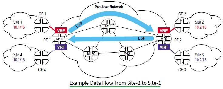
Figure depicts data flow from site-2 (Host-10.2.3.4) to site-1 (Server-10.1.3.8). Following are the steps involved in data flow across BGP/MPLS VPN.
- Host (10.2.3.4) forwards data packets destined for server (10.1.3.8) to the default gateway (CE-2).
- CE-2 does route lookup and forward it(i.e. IPv4 packet) to PE-2.
- PE-2 does route lookup in VRF-Red and obtains required information such as MPLS label (as advertised by PE-1), BGP next hop (loopback address of PE-1) , Outgoing sub-interface for LSP (from PE-2 to PE-1). With the help of these, user traffic is forwarded from PE-2 to PE-1 using MPLS protocol with label stack (i.e. two labels). Here PE-2 will function as ingress-LSR and PE-1 as egress-LSR for the LSP in data flow.
- PE-1 after receiving packet uses bottom label (i.e. 222) to identify CE directly attached to it. This way, PE-1 forwards packet (i.e. IPv4) to CE-1.
- CE-1 forwards packet to server (10.1.3.8).
MPLS-Multi Protocol Label Switching
-
MPLS stands for Multi Protocol Label Switching.
-
MPLS VPN forward packets based on labels instead of IP.
-
Combines best of both overlay and peer to peer model.
-
The P routers in the above network do switching based on label in order to forward VPN data traffic over provider’s backbone.
-
There are two tables maintained in MPLS viz. FEC table by LER (Label Edge Router i.e. CE) and LIB table by LSR (Label Switching Router).
- FEC (Forward Equivalence Class) table = { Destination IP Address, Label Out, Interface }
- LIB (Label Information Base) table = { Label-In, Label-Out, Interface }
LIB and FEC tables are built dynamically using LDP (Label Distribution Protocol) , MPBGP (Multi-protocol Border Gateway Protocol) and RSVP-TE (Resource Reservation Protocol with traffic engineering) .
This guide will help understand functional difference between BGP and MPLS in VPN network.
Advertisement


