 RF
RFOOK vs FSK vs ASK: Modulation Techniques Compared
Advertisement
This page compares OOK vs FSK vs ASK and describes the differences between these modulation techniques.
OOK Modulation | ON OFF Keying Modulation
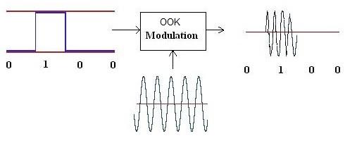
Figure 1: OOK modulation
OOK stands for On-Off Keying. It’s essentially a modified version of ASK (Amplitude Shift Keying). While ASK represents logic-0 with a lower amplitude and logic-1 with a higher amplitude, OOK modulation takes a different approach.
In OOK, there is no carrier transmitted when logic zero is being sent. The carrier is only transmitted during the transmission of logic one. This means the transmitter goes into an IDLE state during the transmission of logic “zero”. This is advantageous for conserving battery power.
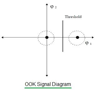
Figure 2: OOK signal diagram
The figure above depicts the OOK signal diagram. Here, φ1 and φ2 represent signal vectors or complex data. The additive noise is represented by the dotted circle around the main signal points.
As shown, one vector (φ1) represents some amplitude on the X-axis, while the other vector (φ2) represents zero value. Since the carrier wave is present and absent at two different logic states, this modulation type is known as ON OFF Keying, or OOK modulation.
ASK Modulation | Amplitude Shift Keying Modulation
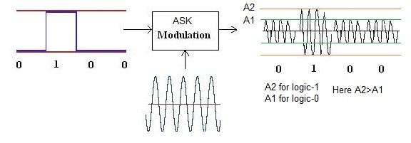
Figure 3: ASK modulation
ASK stands for Amplitude Shift Keying. In ASK modulation, the modulating input is digital, and the carrier is analog.
The carrier wave is present with a higher amplitude (i.e., A2 as shown) in the ASK modulated output when a binary input of ‘one’ is to be transmitted. The logic zero is transmitted with a lower amplitude (i.e., A1) compared to logic-1. Also, refer to 10ASK and 100ASK modulation used in NFC technology.
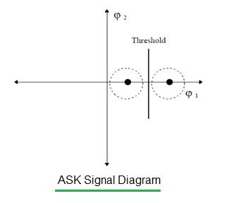
Figure 4: ASK signal diagram
The figure above depicts the ASK signal diagram. As shown, one vector (φ1) represents a higher amplitude compared to the other vector (φ2).
The higher the difference between the two amplitudes, the easier it is to detect and decode the data signal points at the receiver. Because the amplitude value shifts in the transition from one binary logic to the other, this modulation type is known as amplitude shift keying.
FSK Modulation | Frequency Shift Keying Modulation
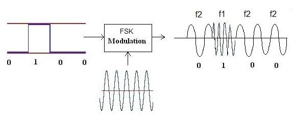
Figure 5: FSK modulation
FSK stands for Frequency Shift Keying. In FSK modulation, the modulating input is digital, and the carrier is analog.
The modulated output will have a frequency of f1 when the binary input is ‘one’ and it will have a frequency of f2 when the binary input is ‘zero’. Also, refer to 2FSK vs 4FSK modulation.
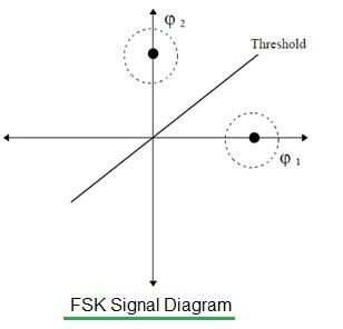
Figure 6: FSK signal diagram
The figure above depicts the FSK signal diagram. As shown, one signal vector (φ1) is represented by some phase, and the other signal vector is represented by a different phase point. These phase points represent two different frequencies.
As the frequency value shifts in the transition from one binary logic to the other, this modulation type is known as frequency shift keying.
OOK vs ASK vs FSK - Key Differences
- FSK modulation performs better compared to OOK/ASK in the presence of interference.
- ASK modulation offers benefits of being more immune to interference compared to OOK modulation.
- It is easier to implement ASK at a lower cost compared to FSK modulation.
- OOK modulation extends battery life as there is no carrier being transmitted during logic-0. Hence, during this time, the transmitter can be in an IDLE state.
Advertisement


