 RF
RFUART vs SPI vs I2C | Difference between UART, SPI and I2C
Advertisement
This page compares UART vs SPI vs I2C interfaces and mentions difference between UART, SPI and I2C in tabular format. It provides comparison between these interfaces based on various factors which include interface diagram, pin designations, data rate, distance, communication type, clock, hardware and software complexity, advantages, disadvanatages etc.
UART Interface
Here are the key features of the UART interface:
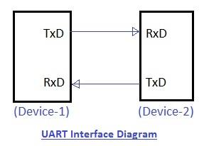
- Full Name: Universal Asynchronous Receiver/Transmitter.
- Data Rate: Supports lower data rates.
- Synchronization: The receiver needs to know the transmitter’s baud rate before communication can begin.
- Protocol: A simple protocol using a start bit (before the data word), stop bits (one or two, after the data word), and a parity bit (even or odd) for basic data formatting. The parity bit aids in single-bit error detection.
- UART Packet Structure: 1 start bit (low level), 8 data bits (including the parity bit), and 1 or 2 stop bits (high level).
- Data Transmission: Data is transmitted byte by byte.
- Clocking: UART generates a clock internally and synchronizes it with the data stream using the start bit’s transition.
- Alias: Often referred to as RS232.
- Long-Distance Communication: For longer distances, the 5V UART signal is converted to higher voltages, such as +12V for logic 0 and -12V for logic 1.
- Interface: The diagram above illustrates a UART interface between two devices.
SPI Interface
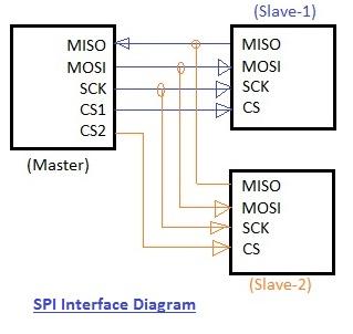
As shown in the figure, a master device can connect to one or more slave devices. The master generates the clock signal for data transfer synchronization. SPI can operate in either half or full-duplex mode.
SPI stands for Serial Peripheral Interface and has four main lines:
- MOSI (Master Output Slave Input): Transfers data from the master to the slave.
- MISO (Master Input Slave Output): Transfers data from the slave to the master.
- SCLK (Serial Clock): The clock output from the master, used for synchronization.
- SS (Slave Select): Used by the master to select a specific slave from multiple slaves by asserting an active-low signal.
I2C Interface
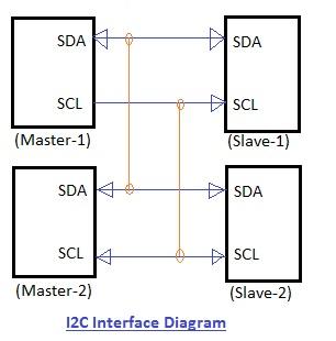
- Full Name: “inter-IC bus” (often shortened to I2C).
- Purpose: A low-speed, two-wire serial data connection bus used in integrated circuits (ICs).
- Usage: Primarily for communication between ICs on the same printed circuit board (PCB).
- Lines: Uses only two lines between multiple masters and multiple slaves: SDA (Serial Data) and SCL (Serial Clock).
- Data Rates: Supports various data rates, from 100 Kbps to 3.4 Mbps, depending on the version.
- Synchronization: Synchronous communication, like SPI, with a common clock signal between masters and slaves.
- Protocol: Employs start and stop bits, along with an ACK (acknowledgment) bit for every 8 bits of data transferred.
Tabular difference between UART, SPI and I2C
Let us compare UART vs SPI vs I2C and summarize difference between UART, SPI and I2C in tabular format.
| Features | UART | SPI | I2C |
|---|---|---|---|
| Full Form | Universal Asynchronous Receiver/Transmitter | Serial Peripheral Interface | Inter-Integrated Circuit |
| Interface Diagram | | | |
| Pin Designations | TxD: Transmit Data RxD: Receive Data | SCLK: Serial Clock MOSI: Master Output, Slave Input MISO: Master Input, Slave Output SS: Slave Select | SDA: Serial Data SCL: Serial Clock |
| Data Rate | Asynchronous communication requires equal data rates. Maximum: ~230 Kbps to 460kbps. | No specified maximum. Typically 10 Mbps to 20 Mbps | 100 kbps, 400 kbps, 3.4 Mbps. Some variants: 10 Kbps and 1 Mbps. |
| Distance | Lower, ~50 feet | Higher | Higher |
| Type of Communication | Asynchronous | Synchronous | Synchronous |
| Number of Masters | One | One | One or more |
| Clock | No common clock. Devices use independent clocks. | Common serial clock between master and slave(s). | Common clock signal between multiple masters and slaves. |
| Hardware Complexity | Lesser | Less | More |
| Protocol | 8 data bits + 1 start bit + 1 stop bit. | Manufacturer-specific protocols require datasheet review for read/write operations. | Start and stop bits. ACK bit for every 8 data bits to confirm reception. |
| Software Addressing | Not needed. One-to-one connection. | Slave select lines address slaves. ‘n’ slave select lines for ‘n’ slaves. | Multiple masters and slaves can communicate. Up to 127 slave devices can be addressed. |
| Advantages | Simple, popular, supported by many devices via 9-pin connector (RS232). Simple protocol, low processing overhead. | Supports full-duplex communication. Separate CS lines allow using multiple chips of the same kind. Higher data rates and longer ranges due to push-pull. Lower power consumption than I2C. | Limited slew rates can be achieved due to open collector design. Multiple masters can be used. Fewer wires (only 2). Simple addressing without CS lines. Bus voltage flexibility. Uses flow control. |
| Disadvantages | Suitable for communication between only two devices. Requires fixed data rate agreement. | Number of CS lines increases with the number of slaves, increasing hardware complexity. Adding a device requires an extra CS line and software changes. Master/slave relationship usually cannot be changed. No flow control. | Increased circuit complexity with more slaves and masters. Half-duplex. Requires software stack for protocol control, leading to processing overhead. |
Conclusion: In summary, UART, SPI, and I2C are popular serial communication protocols, each with distinct characteristics. UART is simple, low speed, full duplex and used for point to point communication. SPI offers high speed, full duplex data transfer with multiple devices on the board. I2C supports low speed, half duplex, multi master, multi slave communication with fewer wires. The choice depends on speed, complexity and the number of connected devices.
Advertisement


