 RF
RFRS232 to TTL Converter Explained
Advertisement
This page explains the differences between RS232 to TTL converters and TTL to RS232 converters.
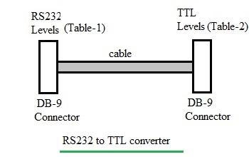
Figure-1: RS232 to TTL converter
Figure-1 shows a simple RS232 to TTL converter. It transforms RS232 signal levels into TTL signal levels. Let’s explore the pin descriptions and signal designations for both sides.
RS232 Side Pin Descriptions
The following table (Table-1) outlines the pin descriptions and signal designations for the RS232 side of the converter:
| RS232 Pin Descriptions | | ---------------------- | -------------------- | | 2 (RXD) | Receive Data input | | 3 (TXD) | Transmit Data output | | 7 (RTS) | Request to Send | | 8 (CTS) | Clear to Send |
Table-1: RS232 Side Pins
TTL Side Pin Descriptions
The following table (Table-2) outlines the pin descriptions and signal designations for the TTL side of the converter:
| TTL Pin Descriptions | | -------------------- | ----------------- | | TXD | 3 (Output) | | RXD | 2 (Input) | | RTS | 7 (Output) | | CTS | 8 (Input) | | GND | 5 (Signal Ground) |
Table-2: TTL Side Pins
TTL to RS232 Converter
The TTL to RS232 converter performs the opposite function of the RS232 to TTL converter. It translates TTL signal levels into RS232 signal levels. You can often use the same cable mentioned earlier, provided it has the correct mating connectors.
Logic Level Differences
It’s important to understand the differences in logic level representation between TTL and RS232. The following table summarizes these differences:
| Logic Type | RS232 | TTL |
|---|---|---|
| Logic 1 () | >+5V (at output), >+2.4V (at input) | 2 V |
| Logic 0 () | <-5V (at output) | <0.2V (at input) |
| 0.8 V |
Advertisement


