
OR vs EX-OR vs EX-NOR Logic Gates: A Comparison
Advertisement
This article explores the differences between OR, EX-OR (XOR), and EX-NOR logic gates, including their truth tables and logic symbols.
OR Logic Gate
The OR gate is a fundamental electronic circuit. It produces a “true” or high output (represented by 1) if one or more of its inputs are true. The OR operation is often represented by a plus sign (+).
OR Gate Symbol and Truth Table
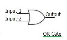
Figure: OR gate logic symbol
The following truth table summarizes the behavior of the OR gate:
| Input-1 | Input-2 | Output |
|---|---|---|
| 0 | 0 | 0 |
| 0 | 1 | 1 |
| 1 | 0 | 1 |
| 1 | 1 | 1 |
Table: OR gate truth table
In essence, the output of an OR gate with inputs and can be represented as:
EX-OR (XOR) Logic Gate
The Exclusive-OR (EX-OR or XOR) gate is a circuit that outputs “true” only if exactly one of its two inputs is true. If both inputs are true, or both are false, the output is false. The EX-OR operation is denoted by an encircled plus sign (⊕).
EX-OR Gate Symbol and Truth Table
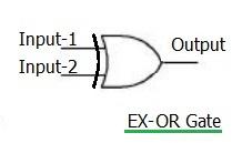
Figure: EX-OR gate logic symbol
Here’s the truth table for the EX-OR gate:
| Input-1 | Input-2 | Output |
|---|---|---|
| 0 | 0 | 0 |
| 0 | 1 | 1 |
| 1 | 0 | 1 |
| 1 | 1 | 0 |
Table: EX-OR gate truth table
Mathematically, the EX-OR operation can be described as:
EX-NOR Logic Gate
The Exclusive-NOR (EX-NOR) gate is the inverse of the EX-OR gate. It outputs “true” if both inputs are the same (either both true or both false), and “false” if the inputs are different. The EX-NOR symbol is an EX-OR gate with a small circle at the output, indicating inversion.
EX-NOR Gate Symbol and Truth Table
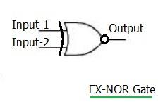
Figure: EX-NOR gate logic symbol
The EX-NOR gate’s truth table is as follows:
| Input-1 | Input-2 | Output |
|---|---|---|
| 0 | 0 | 1 |
| 0 | 1 | 0 |
| 1 | 0 | 0 |
| 1 | 1 | 1 |
Table: EX-NOR gate truth table
The EX-NOR operation can be represented as:
This indicates that the output is the inverse (or complement) of the EX-OR operation.
Advertisement


