802.11 WiFi MAC Frame Format and fields
Advertisement
This article delves into the WLAN MAC protocol, specifically focusing on the WLAN MAC frame format as defined by the IEEE 802.11 WiFi MAC standard. The WLAN MAC frame is composed of three main parts: the MAC header, the body, and the FCS (Frame Check Sequence). The MAC header itself contains several important fields: the frame control field, the duration field, address fields, and the sequence control field.
It is crucial that all stations can properly construct frames for transmission and accurately decode received frames, as outlined in this specification. Let’s break down each part of the 802.11 MAC frame.
- MAC Header: This section includes the frame control field, duration field, address fields (1-3), and the sequence control field.
- Frame Body: The size of this field varies. It contains information specific to the type of frame being transmitted.
- FCS (Frame Check Sequence): This is a 32-bit CRC (Cyclic Redundancy Code) used for error detection.
The MAC frame format dictates a fixed order for these fields within all frames.
The diagram below illustrates the generic MAC frame format according to IEEE 802.11 MAC specifications. Keep in mind that some fields, like Address fields 2 and 3, the sequence control field, address-4, and the frame body, are only present in certain frame types. They are not universal to all frames.

As previously mentioned, the WLAN MAC frame consists of the MAC header, frame body, and FCS fields. The 802.11 MAC header comprises the frame control field, duration/ID field, address fields, and sequence control field.
Let’s explore these MAC header fields in more detail:
1. Frame Control Field
The Frame Control field is further divided into these sub-fields:
- Protocol Version
- Type
- Subtype
- To DS (Distribution System)
- From DS
- More Fragments
- Retry
- Power Management
- More Data
- Wired Equivalent Privacy (WEP)
- Other fields
The following figure shows the composition of the Frame Control field:

2. Duration/ID Field
This field is 16 bits in size and carries the following information:
- In control-type frames of subtype Power Save (PS)-Poll, the Duration/ID field contains the association identity (AID) of the station that transmitted the frame in the 14 least significant bits (LSB), with the 2 most significant bits (MSB) both set to 1. The AID value ranges from 1 to 2007.
- In all other frames, this field contains a duration value specific to each frame type.
- For frames transmitted during the CFP (contention-free period), this field is set to 32,768. If the content of this field is less than 32,768, it is used to update the NAV (Network Allocation Vector).
3. Address Fields
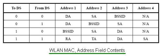
The 802.11 WLAN MAC frame includes four address fields, representing:
- BSSID (Basic Service Set Identifier)
- Source Address (SA)
- Destination Address (DA)
- Transmitting Station Address (TA)
- Receiving Station Address (RA)
Not all frames contain all these address fields; some may be absent depending on the frame type.
The contents of the address fields are illustrated below:

A station uses the content of the address-1 field for receive address matching. In cases where address-1 contains a group address, the BSS-ID is validated to ensure that the broadcast/multicast originated from the same BSS.
- A STA uses the contents of the address-2 field to route acknowledgment if an ACK is required.
- The DA is the destination of the MSDU (or fragment thereof) in the frame body field.
- The SA is the address of the MAC entity that initiated the MSDU (or fragment thereof) in the frame body field.
- The RA is the address of the station (contained within an access point in a WDS) that is the next intended recipient of the frame.
- The TA is the address of the station (contained within the access point in the WDS) that is transmitting the frame.
The data frame BSS-ID is determined as follows:
- If a station is an Access Point or associated with one, the BSSID is the address currently in use by the station within the Access Point.
- If a STA is a member of an IBSS, then the BSSID is the BSSID of the IBSS system.
4. Sequence Control Field
The sequence control field is 16 bits long and consists of two sub-fields: sequence number and fragment number.

- Sequence Number Field: This is a 12-bit field indicating the sequence number of the MSDU/MMPDU. Each MSDU/MMPDU transmitted by a station is assigned a sequence number from a modulo 4096 counter, starting at 0 and incrementing by 1 for each MSDU/M-MPDU transmission. Each fragment of an MSDU/MMPDU contains the assigned sequence number, which remains constant in all re-transmissions.
- Fragment Number Field: This 4-bit field indicates the number of each fragment of an MSDU or MMPDU. The fragment number is set to zero in the first (or only) fragment and incremented by one for each successive fragment. The fragment number also remains constant in all re-transmissions of the fragment.
5. Frame Body Field
The Frame Body is a variable-length field containing information specific to the individual frame types and subtypes. The minimum frame body is 0 octets. The maximum length is defined by the maximum length of (MSDU + ICV + IV), where ICV and IV are WEP fields.
6. FCS Field
The WLAN FCS field is a 32-bit field containing a 32-bit CRC, calculated over all the fields of the MAC header and the Frame Body field (the “calculation fields”).
The FCS is calculated using the following standard generator polynomial of degree 32:
G(x) = x32 + x26 + x23 + x22 + x16 + x12 + x11 + x10 + x8 + x7 + x5 + x4 + x2 + x + 1
The FCS is the 1’s complement of the sum (modulo 2) of the following:
- The remainder of xk * (x31 + x30 + x29 +…+x2 + x + 1) divided (modulo 2) by G(x), where k is the number of bits in the calculation fields.
- The remainder after multiplication of the contents (treated as a polynomial) of the calculation fields by x32 and then division by G(x).
As frames are about to be sent, the FCS is calculated and appended. When a station receives a frame, it calculates the FCS and compares it to the received one. If they match, the frame is assumed to have been transmitted without distortion.
Advertisement
 RF
RF


