Arduino Heartbeat Sensor Interface: Diagram, Code, and Explanation
Advertisement
This document explains how to interface an Arduino board with a heartbeat sensor, including the diagram, working principle, and example code.
About the Heartbeat Sensor
- The sensor outputs a digital square wave.
- The Pulse Width Modulation (PWM) method is used to analyze the output signal.
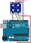
- Connect the sensor’s output to an analog read pin (A0) on the Arduino Uno, as shown below.
Pin Connections
| Heartbeat Sensor | Arduino Uno Board |
|---|---|
| Supply | +5V |
| Ground | GND |
| Output | A0 pin (analog input) |
About the Arduino Board

- The Arduino Uno uses the ATmega328 microcontroller from ATMEL, featuring 32 KB of flash memory, 2 KB of RAM, an 8-bit CPU, and 1 KB of EEPROM.
- It has 6 analog pins for reading voltage (not current) and converting the analog measurement to digital.
- It supports digital pins (0-13) that can function as either inputs or outputs.
- It offers various interfaces such as I2C, digital pins, analog pins, serial communication, and USB.
- Other features include a reset pin, power port, crystal oscillator, and Tx/Rx LEDs.
- You can easily program this open-source prototype board using the Arduino IDE via a USB connection to a laptop.
- The IDE uses simplified C++ programming.
- The board requires 5V DC, which can be supplied using an AC/DC adapter or battery.
Arduino Interfacing with Heartbeat Sensor Diagram

As shown in the figure, the three pins of the heartbeat sensor are connected to the Arduino board as described in the table above.
Arduino Heartbeat Sensor Interface Code
The following Arduino code is compiled and uploaded to the Arduino board using the Arduino IDE. The code determines if the heartbeat is normal based on a comparison between the read value and a normal reference value.
// Libraries for WiFi and MQTT
#include <WiFiClient.h>
#include <Adafruit_MQTT.h>
#include <Adafruit_MQTT_Client.h>

// WiFi and MQTT Settings - Replace with your own credentials
#define WLAN_SSID       "YOUR_WIFI_SSID"
#define WLAN_PASS       "YOUR_WIFI_PASSWORD"
#define MQTT_SERVER      "YOUR_MQTT_SERVER"
#define MQTT_PORT        1883                   // MQTT port numbers
#define MQTT_USERNAME    "YOUR_MQTT_USERNAME"
#define MQTT_PASSWORD    "YOUR_MQTT_PASSWORD"

WiFiClient client;
Adafruit_MQTT_Client mqtt(&client, MQTT_SERVER, MQTT_PORT, MQTT_USERNAME, MQTT_PASSWORD);

// Define the MQTT feed
Adafruit_MQTT_Publish heartbeat_data = Adafruit_MQTT_Publish(&mqtt, MQTT_USERNAME "/feeds/heartbeat_data");

// Heart Rate Variables
const int sensorPin = A0;  // Analog input pin for the sensor
int BPM;                   // Heartbeat value

void setup() {
  Serial.begin(115200);
  delay(10);

  // Connect to WiFi
  Serial.println(); Serial.println();
  Serial.print("Connecting to ");
  Serial.println(WLAN_SSID);

  WiFi.begin(WLAN_SSID, WLAN_PASS);
  while (WiFi.status() != WL_CONNECTED) {
    delay(500);
    Serial.print(".");
  }
  Serial.println();

  Serial.println("WiFi connected");
  Serial.println("IP address: "); Serial.println(WiFi.localIP());

  // Connect to MQTT
  Serial.print("Connecting to MQTT... ");

  uint8_t retries = 3;
  while ((connectMQTT()) && --retries) {
       delay(100);
  }

  if(!mqtt.connected()){
       Serial.println("MQTT connection FAILED!");
       while(1);
  }

  Serial.println("MQTT Connected!");
}

void loop() {
  // Ensure the connection to the MQTT server is alive (this will make the client reconnect if necessary).
  MQTT_connect();

  // Read the sensor value
  int sensorValue = analogRead(sensorPin);

  // Simulate Heart Rate Calculation (replace with a proper algorithm)
  // This is a very basic example, real-world sensors need more sophisticated calculations.
  BPM = map(sensorValue, 0, 1023, 30, 120);  // Map the analog reading to a BPM range

  // Print the raw sensor value and calculated BPM
  Serial.print("Sensor Value: ");
  Serial.print(sensorValue);
  Serial.print(", BPM: ");
  Serial.println(BPM);


  // Publish the heartbeat data
  if (heartbeat_data.publish(BPM)) {
    Serial.println("MQTT Publish Success!");
  } else {
    Serial.println("MQTT Publish Failed!");
  }

  // Check Heart Rate and Print Status
  if (BPM >= 80) {
    Serial.println("Rapid Heartbeat!");
  } else if (BPM <= 32) {
    Serial.println("Low Heartbeat!");
  } else {
    Serial.println("You are FINE..!!");
  }

  delay(2000); // Delay between readings
}


boolean connectMQTT() {
  int8_t ret;

  // Stop if already connected.
  if (mqtt.connected()) {
    return true;
  }

  Serial.print("Connecting to MQTT... ");

  uint8_t retries = 3;
  while ((ret = mqtt.connect()) != 0) { // connect will return 0 for connected
       Serial.println(mqtt.connectErrorString(ret));
       Serial.println("Retrying MQTT connection in 5 seconds...");
       mqtt.disconnect();
       delay(5000);  // wait 5 seconds
       retries--;
       if (retries == 0) {
         // basically die and wait for WDT reset
         return false;
       }
  }
  Serial.println("MQTT Connected!");
  return true;
}


void MQTT_connect() {
  int8_t ret;

  // Stop if already connected.
  if (mqtt.connected()) {
    return;
  }

  Serial.print("Connecting to MQTT... ");

  uint8_t retries = 3;
  while ((ret = mqtt.connect()) != 0) { // connect will return 0 for connected
       Serial.println(mqtt.connectErrorString(ret));
       Serial.println("Retrying MQTT connection in 5 seconds...");
       mqtt.disconnect();
       delay(5000);  // wait 5 seconds
       retries--;
       if (retries == 0) {
         // basically die and wait for WDT reset
         while (1);
       }
  }
  Serial.println("MQTT Connected!");
}
Important Notes:
- Replace Placeholders: Make sure to replace
YOUR_WIFI_SSID,YOUR_WIFI_PASSWORD,YOUR_MQTT_SERVER,YOUR_MQTT_USERNAME, andYOUR_MQTT_PASSWORDwith your actual credentials. - Install Libraries: You will need to install the
WiFiClientandAdafruit_MQTT_Clientlibraries in the Arduino IDE. Go to Sketch -> Include Library -> Manage Libraries… and search for them. - MQTT Broker: You need an MQTT broker. The code is designed to work with Adafruit IO. You will need an Adafruit IO account.
- Heartbeat Calculation: The provided
BPM = map(sensorValue, 0, 1023, 30, 120);line is a very rudimentary simulation of heart rate calculation. Real-world heartbeat sensors output complex data. You will need to research and implement a proper algorithm for converting the sensor readings into a meaningful BPM (beats per minute) value. - Analog Input: This code assumes the heartbeat sensor’s output is connected to analog pin A0 of the Arduino Uno.
- Error Handling: This code includes basic error handling for MQTT connections. In a production environment, you would want to add more robust error handling.
- Proper Circuit: Double-check the wiring of your heartbeat sensor and the Arduino board to ensure proper connections.
Conclusion
This document demonstrated how to interface a heartbeat sensor with an Arduino Uno board. Arduino boards can be used to interface with various types of sensors for a wide range of applications. Some common sensors used with Arduino include sound sensors, gyro sensors, LDR sensors, GPS sensors, color sensors, and pH sensors.
Advertisement
 RF
RF


