Interfacing Color Sensor with Arduino: Guide, Diagram & Code
Advertisement
This document explains how to interface an Arduino with a color sensor. It covers the necessary diagrams, working principles, and example code.
About the Color Sensor
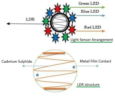
The color sensor is used to detect the RGB (Red, Green, Blue) coordinates of a color. It works by emitting white light onto an object and recording the reflected light using photodiodes. Color filters are used to convert the amount of light into current.
We will use the TCS3200 color sensor for this explanation. The TCS3200 IC contains a current-to-frequency converter. The RGB values are then processed to determine the exact color combination.

For more information, refer to the advantages and disadvantages of color sensors.
Color Sensor Pin Designations
- GND: Power supply ground
- OE: Enable for output frequency (active low)
- OUT: Output frequency
- S0, S1: Output frequency scaling selection inputs
- S2, S3: Photodiode type selection inputs
- VDD: Voltage Supply
The control pins S2 and S3 are used to select which color is read by the photodiode. The combinations are as follows:
- S2/S3 -> Low/Low: Selects Red filter
- S2/S3 -> Low/High: Selects Blue filter
- S2/S3 -> High/High: Selects Green filter
- S2/S3 -> High/Low: No filter
About the Arduino Board
For this project, we’ll be using the Arduino Uno board.

- The Arduino Uno houses the ATmega328 microcontroller from ATMEL. This microcontroller contains flash memory (32 KB), RAM (2 KB), 8-bit CPU and 1 KB EEPROM.
- It supports 6 analog pins which read voltage (not current). Internally, it converts analog measurements to digital.
- It supports digital pins (0 to 13) which can function either as input or output.
- It has various interfaces: I2C, digital pins, analog pins, serial communication, USB etc.
- It also has a reset pin, power port, crystal oscillator and Tx/Rx LEDs.
- This open-source prototype board can be easily programmed using the Arduino IDE and a USB interface between the laptop/PC and the board.
- The IDE uses a simplified C++ program.
- The board requires 5V DC, which can be supplied using an AC/DC adapter or a battery.
Arduino Interfacing with Color Sensor Diagram and Working
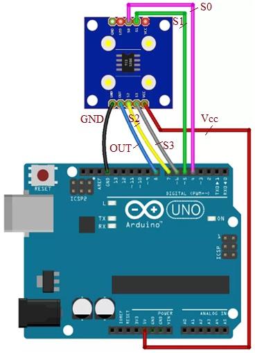
The following diagram shows how to interface the color sensor with an Arduino Uno board.

The connections between the Arduino and the color sensor are as follows:
| Color sensor TCS3200 | Arduino board |
|---|---|
| S0 | Pin 4 |
| S1 | Pin 5 |
| Vcc | +5V |
| S2 | Pin 7 |
| S3 | Pin 6 |
| OUT | Pin 8 |
| GND | GND |
Arduino Color Sensor Interface Code
The following Arduino code is compiled and uploaded to the Arduino board using the Arduino IDE.
// TCS3200 pins connections with arduino board
#define S0 4
#define S1 5
#define S2 6
#define S3 7
#define sensorOut 8

// frequency read by the photo-diodes are stored in following variables
int redFrequency = 0;
int greenFrequency = 0;
int blueFrequency = 0;

void setup() {
  pinMode(S0, OUTPUT);
  pinMode(S1, OUTPUT);
  pinMode(S2, OUTPUT);
  pinMode(S3, OUTPUT);
  pinMode(sensorOut, INPUT);

  digitalWrite(S0,HIGH);
  digitalWrite(S1,LOW);
  Serial.begin(9600);
}

void loop() {
  digitalWrite(S2,LOW);
  digitalWrite(S3,LOW);
  // Reading the output frequency
  redFrequency = pulseIn(sensorOut, LOW);
  Serial.print("R = ");
  Serial.print(redFrequency);
  delay(100);

  digitalWrite(S2,HIGH);
  digitalWrite(S3,HIGH);
  // Reading the output frequency
  greenFrequency = pulseIn(sensorOut, LOW);
  Serial.print(" G = ");
  Serial.print(greenFrequency);
  delay(100);

  // Setting BLUE (B) filtered photodiodes to be read
  digitalWrite(S2,LOW);
  digitalWrite(S3,HIGH);
  blueFrequency = pulseIn(sensorOut, LOW);
  Serial.print(" B = ");
  Serial.println(blueFrequency);
  delay(100);
}
Conclusion
In this guide, we’ve covered interfacing a color sensor with an Arduino Uno board. Arduino boards are also used for interfacing with many other types of sensors for various applications.
Some typical sensors interfaced with Arduino include sound sensors, gyro sensors, LDR sensors, GPS sensors, heartbeat sensors, pH sensors, etc.
Advertisement
 RF
RF


