RF Signal Generator and Vector Signal Analyzer: Block Diagram and Applications
Advertisement
In the world of wireless communication and testing, RF signal generators and vector signal analyzers (VSA) play a pivotal role. These devices are crucial for generating and analyzing radio frequency signals, ensuring precision and accuracy in modern communication systems. This article delves into the working of RF signal generators, explains the VSA block diagram in detail, and highlights their combined application in signal testing and analysis. Whether you are a professional engineer or a student, this guide will provide valuable insights into these essential tools.
The signal generation and analysis is required for testing of various wireless devices before they come to commercial market. It also covers Test and measurement companies manufacturing RF signal generator and RF signal analyzer for vector signal generation and vector signal analysis. It covers Agilent 89600 VSA showing various baseband measurements of wimax modulated signal.
Wireless devices include but not limited to wimax, wlan, zigbee, lte and more.
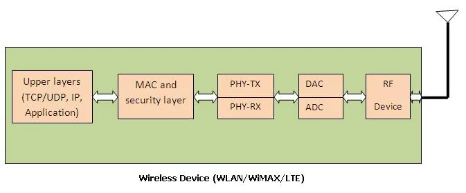
Before we move to signal generation and analysis let us understand what a common typical wireless device made of. Wireless device usually will be compliant to some standard e.g. IEEE, 3GPP etc. There are various technologies which fall under these standards such as WLAN, WiMAX, LTE, Zigbee, Bluetooth, GSM, CDMA etc. This standard compliant device will have PHY layer called as baseband, MAC layer, ADC/DAC, RF chip and upper layers (TCP/UDP, IP and application), antenna. Following figure depicts modules in such wireless device.
As mentioned in the block diagram of wireless device, it consists of two main parts transmitter and receiver at each layer.
RF signal generator for vector signal generation
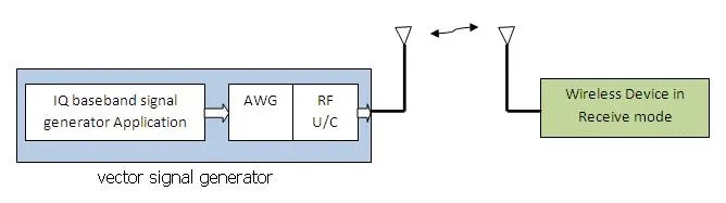
In order to test the receiver part signal generator is required, which will generate standard compliant signal. For example if we want to test wimax device’s receiver part, signal generator need to have wimax compliant IQ baseband generator application or IQ vector file. This IQ file coupled with RF will generate modulated RF signal. This modulated wimax compliant RF signal is fed to the device under test.
As mentioned in the figure below signal generation is done using RF vector signal generator which houses Waveform generator and RF frequency up converter.
Wimax device will receive this signal, decode the same and will follow certain software states as developed by its protocol developers. If the circuit of wireless device is under development various RF, PHY, MAC and upper layer tests can be conducted. If the circuit is not open PHY layer header and MAC layer frame testing can be performed.
If the circuit is open, RF received signal after down conversion or after RF chip can be checked for power level as well as response. Received IQ signal can be checked, decoded data after PHY can be compared with raw data used for IQ baseband signal generation by signal generator. Received MAC frames can be checked using MAC header checksum and CRC of entire MAC frame.
RF signal Analyzer for vector signal analysis
In order to test the transmitter part signal analyzer is required, which will analyze RF signal transmitted by wireless device. For example if we want to test wimax device’s transmitter part, following set up need to be done.
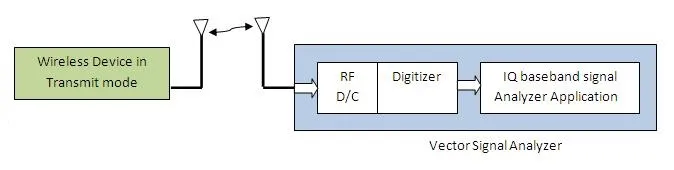
As mentioned in the figure signal analysis is done using RF vector signal analyzer which houses RF frequency down converter and digitizer.
As mentioned in the setup, wimax device will generate standard compliant wimax RF modulated signal. This signal is fed to the RF vector signal analyzer which will perform signal analysis. This Vector signal analyzer has RF part and baseband analyzer application running on the same instrument. Various RF and PHY measurements can be cross checked using this application. Following diagram depicts the same by Agilent Vector signal analyzer application 89600.
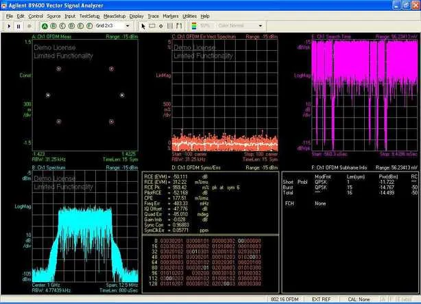
Agilent 89600 VSA is very popular IQ baseband signal analyzer in the industry. VSA in the figure above shows IQ constellation diagram, EVM versus subcarrier, instantaneous power versus time,power spectrum,useful baseband parameters such as frequency offset,IQ offset,EVM,CPE,gain imbalance and PHY layer frame information.
Conclusion
RF signal generators and VSAs are indispensable in the testing and development of RF and wireless systems. By understanding their working principles and block diagrams, engineers and enthusiasts can better appreciate their role in ensuring robust communication systems. As technology continues to evolve, mastering these tools will remain critical for achieving optimal performance and innovation in RF signal processing.
Various devices and applications are available to help perform generation and analysis tests. Channel emulator can also be used as real time channel for particular standard to perform accurate pre-deployment tests for the wireless device.