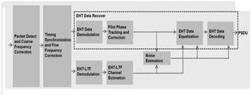
WiFi 7 Transmitter Measurements: EVM, Spectral Flatness, and Emission Mask Explained
Advertisement
In Wi-Fi 7 (IEEE 802.11be), transmitter measurements are critical for ensuring that devices meet performance and regulatory requirements. These measurements help evaluate the quality and compliance of transmitted signals, affecting overall network performance and interoperability.
Key transmitter measurements include Error Vector Magnitude (EVM), Spectral Flatness, and Emission Mask.
Error Vector Magnitude (EVM)
 EVM Graph
EVM is a measure of the modulation quality of the transmitted signal and reflects the difference between the ideal and actual transmitted signal points in a constellation diagram. It indicates how accurately the signal represents the data being transmitted. The following graph mentions the EVM measurement technique.
 EVM converter
Definition and Importance
EVM quantifies the deviation of the actual transmitted signal from the ideal reference signal. Lower EVM values indicate higher signal quality and less distortion, which translates to better performance, particularly in high modulation schemes like 4096-QAM used in Wi-Fi 7. It is expressed as a percentage or in decibels (dB), with lower values indicating better signal quality. EVM can also be represented in rms (%) as mentioned in the formula above. The following EVM formula is commonly used to calculate EVM for ‘N’ symbols of any modulation scheme.
 EVM calculation formula
Example:
If EVM is -32 dB
EVM rms % = 10(-32/20) x 100 = 10-1.6 x 100 = 2.51 %
Measurement
EVM is measured by comparing the actual received symbols with the ideal transmitted symbols in a constellation diagram. For Wi-Fi 7, the EVM requirements become stricter as modulation order increases. For example, as mentioned in the 802.11be, wifi 7 EVM table is as follows :
- 256-QAM might require EVM to be below -32 dB.
- 1024-QAM require EVM to be below -35dB
- 4096-QAM, which Wi-Fi 7 supports, requires even lower EVM (better signal quality), often below -38 dB.
 WiFi 7 EVM Table
Factors Affecting EVM
- Non-linearities in the transmitter components, such as amplifiers and mixers.
- Phase noise and frequency errors.
- Interference and noise from the environment.
Spectral Flatness
Spectral Flatness measures the uniformity of the signal’s power distribution across its occupied bandwidth. It ensures that the transmitter power is evenly distributed, without significant variations, over the entire channel.
 WiFi 7 spectral flatness
Image Courtesy : Rohde & Schwarz
Definition and Importance
Spectral Flatness indicates how evenly the power is spread across the frequency spectrum of the transmitted signal. Uniform power distribution helps minimize interference with adjacent channels and ensures that all parts of the transmitted signal contribute equally to data transmission.
Measurement
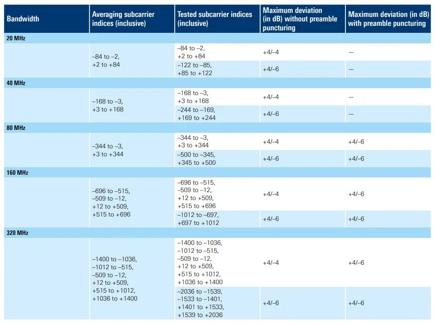
Spectral flatness is measured by comparing the power levels of different subcarriers within an OFDM signal. Deviations from flatness are specified as a maximum allowable variation, typically measured in dB, from the average power level across the bandwidth. For Wi-Fi 7, spectral flatness specifications are stringent due to wider bandwidths (up to 320 MHz) and the need to maintain performance over large channel widths.
 EHT PPDU spectral flatness as per IEEE 802.11be
Image Courtesy : Rohde & Schwarz
Factors Affecting Spectral Flatness
- Imbalance in the transmitter’s RF components.
- Imperfections in the digital-to-analog conversion process.
- Non-uniform amplifier gain across frequencies.
Emission Mask
The Emission Mask defines the limits of the signal’s power spectral density outside its intended bandwidth, ensuring that the transmitter does not produce excessive out-of-band emissions that could interfere with adjacent channels. Following is the emission mask for 320 MHz bandwidth.
 WiFi-7 Spectral Emission Mask
Image Courtesy : Rohde & Schwarz
Definition and Importance
The emission mask sets a limit on the power levels that a transmitter can emit outside its assigned channel bandwidth. It helps reduce interference with neighboring channels and ensures that devices operate within regulatory limits, maintaining coexistence with other wireless services.
 WiFi-7 Transmit Mask Values for all Channel Bandwidths
Measurement
The emission mask is measured by analyzing the power spectral density of the transmitted signal across a range of frequencies that extend beyond the channel bandwidth. The power at specific offsets from the channel edge (e.g., ±20 MHz, ±40 MHz) must fall within predefined limits. Wi-Fi 7 has more stringent emission mask requirements to accommodate wider channels and higher data rates, thus ensuring minimal interference with adjacent channels.
Factors Affecting Emission Mask Compliance
- High peak-to-average power ratios (PAPR) in OFDM signals.
- Non-linear distortion from transmitter amplifiers.
- Filtering imperfections.
 WiFi 7 Spectrum Emission Mask with puncturing
Image Courtesy : Rohde & Schwarz
The spectrum mask for an 80 MHz PPDU with a punctured middle subchannel is shown in the figure above.
Summary
- EVM assesses the modulation quality by measuring the deviation of transmitted signal points from ideal locations in a constellation diagram. Wi-Fi 7’s high-order modulation schemes like 4096-QAM require lower EVM values to maintain data integrity.
- Spectral Flatness ensures that the signal’s power is uniformly distributed across its occupied bandwidth, crucial for efficient spectrum usage and reducing adjacent channel interference.
- Emission Mask limits out-of-band emissions, ensuring that transmitters do not cause interference with adjacent channels or other spectrum users, meeting regulatory requirements.
- All these measurements are critical for evaluating the performance and regulatory compliance of Wi-Fi 7 transmitters, enabling high throughput, low latency, and reliable operation.
- The popular vendors of RF/PHY test systems as per WiFi 7 specifications defined in IEEE 802.11be include LitePoint, Keysight Technologies, and R&S, etc.
Advertisement
 RF
RF


