 RF
RFMechanical vs Electrical Oscillators: A Comparison
Advertisement
This article compares mechanical and electrical oscillators, highlighting their differences. We will also derive the equation of an electrical oscillator equivalent to a harmonic oscillator.
Introduction
Oscillators are fundamental components in most communication systems and test & measurement equipment. Their specifications and tolerances directly impact the performance of these systems. Several key parameters are considered during oscillator design, including:
- Frequency sensitivity
- Frequency stability (short-term and long-term drifts)
- Oscillator noise
- Amplitude stability
Mechanical Oscillator (Harmonic Oscillator)
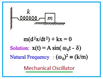
- Figure 1 depicts a simple mechanical oscillator, such as a mass attached to a spring. This structure is similar to a pendulum and is also known as a harmonic oscillator.
- When a body attached to a spring is displaced from its equilibrium position, the spring exerts a restoring force, pulling it back towards equilibrium. This force causes the system to oscillate or undergo periodic motion.
- The relationship between period (T) and frequency (f) of oscillation is: .
- Angular frequency (ω) is approximately times the frequency: .
- When the restoring force is directly proportional to the displacement from equilibrium, the motion is called simple harmonic motion, and the oscillator is a Harmonic Oscillator.
Electrical Oscillator
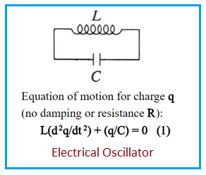
- Figure 2 shows the electrical analogy of a mechanical oscillator. This is an example of an electronic or electrical oscillator. Different types exist, including RC oscillators, LC oscillators, and crystal oscillators.
- An LC circuit consists of an inductor (L) and a capacitor (C). Initially, the capacitor is charged, inducing a current in the inductor. Subsequently, the current and voltage oscillate harmonically according to the following equations:
Deriving the Differential Equation for an Electrical Oscillator
Let’s derive the differential equation that represents an electrical oscillator:
-
The capacitor discharges (or charges) through the inductor. Therefore, the current (I) in the inductor and the charge (Q) on the capacitor are related as: .
-
Consequently, the voltage across the inductor is related to the second time derivative of the charge as: .
-
In an LC circuit, the voltage across the inductor must be the same as the voltage across the capacitor. Hence, .
-
Comparing the last two equations, we get: .
-
This second-order differential equation for charge has the form of a harmonic oscillator.
Advertisement


