Error Vector Magnitude (EVM) Basics
Advertisement
This page describes EVM (Error Vector Magnitude) basics, the EVM equation, and its significance in wireless systems. EVM, or Error Vector Magnitude, provides insight into the quality of the modulated signal/symbol. This modulated signal originates when bits are mapped to symbols in complex modulation systems such as QPSK, 16-QAM, 64-QAM, etc. It is also referred to as RCE (Relative Constellation Error).

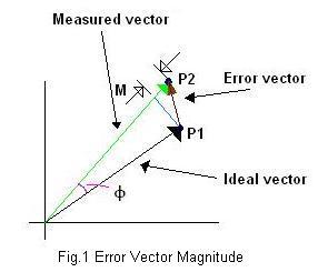
Error Vector magnitude for a symbol is described in Fig. 1, where P1 is the ideal constellation point and P2 is the measured constellation point with some impairments. Impairments may be of different types in the RF and baseband chain. They include IQ mismatch (gain, phase, DC offset), frequency offset, phase noise, AM-AM distortion, AM-PM distortion, AWGN, multipath fading (fixed, time-varying), and interference, etc. From the figure, it’s clear that M and Φ are magnitude and phase errors, respectively, between two constellation points.
EVM Equation

Where:
- P1 = I1 + j*Q1 is the ideal/reference symbol vector
- P2 = I2 + j*Q2 is the measured symbol vector
WiMAX EVM Equation

Here, the Error Vector Magnitude is calculated for all the frames (Nf) and all packets (Lp) in each frame and all the symbols (total data and pilots carriers in each symbol are 200) in each packet. Then, it is averaged to obtain the RMS value of the EVM as shown in the EVM equation.
EVM per subcarriers and EVM per symbols for the OFDM physical layer as per fixed WiMAX specifications described in the IEEE 802.16-2004 standard is explained in the physical layer measurements page.
EVM Conversion
EVM dB = 20 * log10 (EVM rms)
EVM of QPSK Constellation
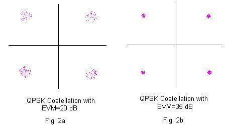
Higher EVM dB results in closer constellation points as shown in fig. 2b, and lesser EVM(dB) results in scattered constellation points as shown in fig. 2a for the QPSK constellation diagram.

Fig.2 EVM constellation for two different Error Vector Magnitude values
Advertisement
 RF
RF


