 RF
RFOMT vs TRF: Understanding the Key Differences
Advertisement
This article compares OMT (Orthomode transducer) and TRF (Transmit Reject Filter) and highlights the key differences between them.
What is an Orthomode Transducer (OMT)?
An Orthomode Transducer (OMT) is used in conjunction with a feed horn antenna to receive electromagnetic (EM) waves from a satellite or transmit EM waves towards a satellite. It essentially acts as an interface.
The OMT transforms a circular waveguide shape into two rectangular waveguides. One of these rectangular waveguides connects to the transmit (Tx) chain, while the other connects to the receive (Rx) chain. In addition to separating transmit and receive paths, an OMT can also convert a circularly polarized signal into linearly polarized signals, specifically horizontal and vertical polarizations.
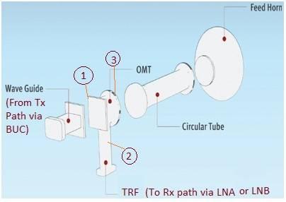
Figure: OMT (Orthomode Transducer) for a C-band VSAT terminal.
As illustrated in the figure, the OMT has three ports:
- Port 1: Connected to the BUC (Block Upconverter).
- Port 2: Connected to the LNA (Low Noise Amplifier) or LNB (Low Noise Block Converter) via a TRF.
- Port 3: Connected to the circular tube of the feed horn antenna.
The TRF (Transmit Reject Filter), which we’ll discuss next, plays a crucial role in blocking the transmit power from reaching the sensitive LNA/LNB, protecting it from damage.
Here are typical specifications for a C-Band OMT:
- Frequency Band: Tx/Rx frequencies in C-band
- Insertion Loss: 0.3 to 0.6 dB
- Isolation: 30 to 35 dB
What is a Transmit Reject Filter (TRF)?
A Transmit Reject Filter (TRF) is a specialized filter designed to reject frequencies intended for transmission, preventing them from reaching the receive path of a satellite earth station.
In essence, the TRF blocks undesired transmit frequencies from reaching sensitive receiver modules like the LNA or LNB (which is a combination of an LNA and a down-converter). This is crucial for preventing damage to the LNA/LNB from high-power transmit signals.
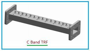
Figure: C-Band Transmit Reject Filter (TRF) used for INSAT.
Typical specifications of a C-Band TRF are as follows:
- Pass Band: 4.5 to 4.8 GHz (Receive Band used in INSAT)
- Reject Band: 6.725 to 7.025 GHz (Transmit Band used in INSAT)
- Insertion Loss: Approximately 0.5 dB (Maximum)
- Rejection: 80 dB (minimum)
- VSWR: 1.3:1 (Maximum)
- Other Considerations: Dimensions, Operating Temperature range, Flanges, etc.
Difference Between OMT and TRF
Here’s a summary of the key differences between an OMT and a TRF:
- Ports and Connections:
- OMT: Has three ports and is connected between the horn feed, Tx path, and Rx path.
- TRF: Has two ports and is connected between the Rx port of the OMT and the LNA/LNB.
- Frequency Handling:
- OMT: Passes both the Transmit and Receive frequencies at different polarizations (horizontal and vertical linear polarizations).
- TRF: Blocks transmit frequencies to prevent damage to the LNA in the receiver chain.
- Function:
- OMT: A polarization duplexing device, separating signals based on their polarization.
- TRF: A passive RF filter designed to reject specific frequencies.
Advertisement


