 RF
RFCapacitive Level Sensor Basics
Advertisement
This page covers the basics of capacitive level sensors, including their operational principles and working with a diagram.
The capacitive sensor is used for liquid level sensing utilizing capacitive-to-digital converters (CDCs). Capacitance refers to a body’s ability to store electrical charge.
It is expressed by the following equation:
C = Q/V
Where:
Q= Charge on the capacitorV= Voltage across the capacitor
Capacitance of two parallel plates with area ‘A’ and separated by distance ‘d’ is expressed as follows:
C = ε₀ * εᵣ * (A/d)
Where:
C= Capacitance in faradsA= Area of overlap of plates (a x b)d= Distance between two platesε₀= Permittivity of free space = 8.854 x 10�?�¹² F/mεᵣ= Relative permittivity of the dielectric material between the two plates
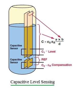
Figure 1: Liquid level sensing using capacitive sensor and capacitance-to-digital converters
Figure 1 depicts the working operation of capacitive level sensing. A simple technique to monitor liquid level is shown in the figure using two parallel plate capacitive sensors. One pair of capacitive sensors (S2) is used as a reference. The other plate of the sensor (S1) is used to measure the liquid level in reference to the first one.
As shown in the figure, if the liquid level changes, the amount of dielectric material between the plates of S1 changes. This causes the capacitance to vary accordingly. Due to the fact that εᵣ (Water) is significantly greater than εᵣ (Air), the capacitance of the sensor can be roughly taken as the capacitance of the submerged liquid section.
From the formulas for C1 and C2 of sensors S1 and S2 respectively, the level of liquid can be derived as C1/C2 (i.e., the ratio of C1 with C2).
Capacitance to digital converters are used to read capacitance and convert it to a digital value for further processing or to initiate an action according to the level, such as switching off or switching on a motor.
Advertisement


