 RF
RFWiFi 7 Physical Layer: Transmitter Modules for APs and STAs
Advertisement
The physical layer (PHY) of WiFi 7 represents a significant leap forward compared to WiFi 6 (802.11ax). Let’s dive into the Wi-Fi 7 PHY and its modules for the Access Point (AP) and Station (STA) transmitter components using a block diagram approach. The IEEE 802.11be standard defines WiFi 7 PHY specifications. Wi-Fi 7’s physical layer is engineered to meet the growing demands of modern wireless networks, supporting applications that require high data rates and low latency, like AR/VR, 4K/8K streaming, and real-time gaming.
802.11be WiFi-7 PHY Parameters
The following table outlines the PHY parameters specified in the WiFi-7 802.11be IEEE standard.
| Specifications | IEEE 802.11be (EHT) |
|---|---|
| Supported bands | 2.4 GHz, 5 GHz, 6 GHz |
| Channel Bandwidth (MHz) | 20, 40, 80, 160, 320 |
| Subcarrier Spacing (KHz) | 78.125 |
| Symbol time (µs) | 12.8 |
| Cyclic prefix (µs) | 0.8 , 1.6 , 3.2 |
| MU-MIMO | Uplink and downlink Spatial Streams 16 x 16 (including MU-MIMO) |
| Modulation | OFDM, OFDMA |
| Data subcarrier modulation | BPSK, QPSK, 16QAM, 64QAM, 256QAM, 1024QAM, 4096QAM |
| FEC Coding | BCC , LDPC |
As shown in the table, WiFi 7 PHY aims for extremely high throughput (EHT) by improving existing features and adding new ones.
Key enhancements in Wi-Fi 7 PHY compared to its predecessors (11n, 11ac, 11ax) include the following:
- Channel bandwidths up to 320 MHz: This is double the 160 MHz in Wi-Fi 6, enabling significantly higher data rates.
- 4096-QAM: WiFi-7 uses 4096-QAM (Quadrature Amplitude Modulation), a step up from 1024-QAM in Wi-Fi 6, increasing the amount of data carried per symbol.
- Multi-Link Operation (MLO): Wi-Fi 7 supports MLO, which can utilize multiple frequency bands (2.4 GHz, 5 GHz, and 6 GHz) simultaneously, optimizing data transmission and improving reliability.
- Enhanced Resource Unit (RU) Allocation: Wi-Fi 7 allows for more flexible and efficient use of the spectrum through improved RU allocation.
- Preamble Puncturing: This feature allows excluding parts of the spectrum affected by interference, improving throughput in challenging environments.
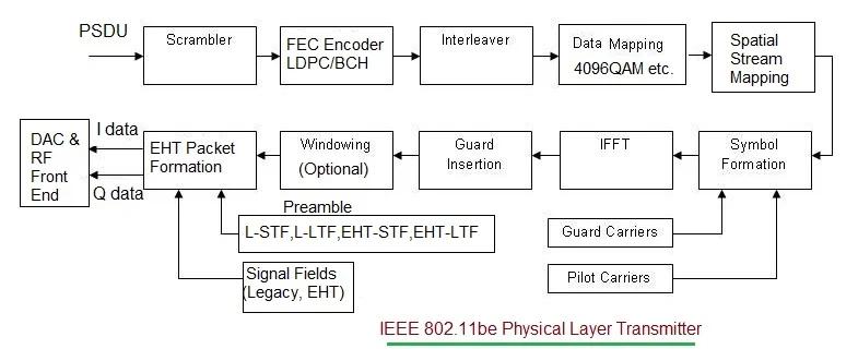
WiFi 7 802.11be Physical Layer Transmitter for AP and STA
The transmitter part of the WiFi 7 PHY for both Access Point and Station includes common modules as follows:
- Scrambler: Randomizes the data to prevent long sequences of zeros or ones, ensuring a balanced signal for subsequent modulation steps.
- Forward Error Correction (FEC) Encoder: Enhances data integrity. Wi-Fi 7 utilizes LDPC (Low-Density Parity-Check) codes for robust error correction, improving data transmission reliability.
- Interleaver: Rearranges the coded bits to spread out errors caused by noise and fading, making them easier to correct during reception.
- Modulator: Wi-Fi 7 supports higher-order modulation schemes up to 4096-QAM, mapping interleaved bits onto complex symbols corresponding to the chosen modulation scheme.
- Resource Unit (RU) Mapper: Assigns data symbols to specific subcarriers within the allocated RUs. Wi-Fi 7 offers enhanced flexibility in RU allocation, enabling more efficient spectrum use.
- Inverse Fast Fourier Transform (IFFT): Converts the frequency domain symbols into time-domain signals, forming the OFDM (Orthogonal Frequency Division Multiplexing) waveform.
- Cyclic Prefix (CP) Insertion: Adds the CP to each OFDM symbol to protect against inter-symbol interference (ISI) caused by multipath propagation, ensuring signal integrity across various environments.
- Windowing and Filtering: Smooths signal transitions, reducing out-of-band emissions and helping meet regulatory spectral masks.
- Digital-to-Analog Converter (DAC): Converts the digital time-domain OFDM signal into an analog waveform suitable for over-the-air transmission.
- RF Front-End: Amplifies, filters, and up-converts the analog signal to the appropriate RF channel for transmission. It includes power amplifiers, mixers, and filters specific to the 2.4 GHz, 5 GHz, or 6 GHz bands.
802.11be WiFi 7 Physical Layer Receiver
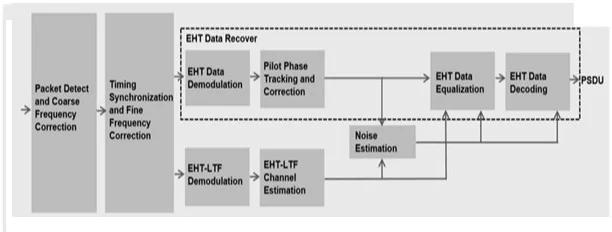
Image Courtesy: The MathWorks, Inc.
Here are the common modules in the 802.11be physical layer receiver:
-
Signal Reception and RF Front-End:
- Antenna and RF Front-End: The signal is received via the antenna and processed by the RF front-end, which amplifies the signal, downconverts it from RF to baseband, and filters it to isolate the desired signal.
-
Analog-to-Digital Conversion (ADC):
- The analog signal is converted into a digital signal using an ADC, preparing it for further digital signal processing.
-
Time Synchronization and Frequency Offset Correction:
- Time Synchronization: Ensures receiver alignment with the start of each OFDM symbol, critical for accurate demodulation.
- Frequency Offset Correction: Compensates for any frequency shifts due to Doppler effects or oscillator mismatches between the transmitter and receiver. This step uses pilot signals embedded in the data stream for precise corrections.
-
FFT Processing:
- FFT (Fast Fourier Transform): Converts the received time-domain OFDM symbols into the frequency domain, allowing the receiver to separate the subcarriers and recover the transmitted data.
-
Channel Estimation and Equalization:
- Channel Estimation: Utilizes known pilot symbols embedded within the OFDM symbols to estimate the channel response, determining how the channel has altered the transmitted signal, including effects like multipath fading and phase shifts.
- Channel Equalization: Corrects the signal by reversing the effects of the channel using the estimated channel response.
-
EHT (Extremely High Throughput) Data Demodulation:
- Demodulation: Maps the received constellation points back to data bits. For 4096-QAM, this involves identifying each point within a dense 4096-point constellation, demanding high accuracy due to the small distance between points.
-
De-Interleaving and FEC Decoding:
- De-Interleaving: Reorders the received bits into their original sequence to reverse the interleaving process done at the transmitter. This helps correct burst errors that affect multiple consecutive bits.
- FEC Decoding (LDPC/BCH): Applies Forward Error Correction using LDPC or BCH decoding algorithms to correct errors introduced during transmission.
-
Descrambling:
- The descrambler reverses the scrambling applied at the transmitter to recover the original data stream.
-
MAC Layer Processing:
- After the physical layer processing is complete, the demodulated and decoded data is passed to the MAC layer for further processing, such as frame assembly, error checking, and acknowledgment handling.
Key Differences in AP and STA Transmitter Design
While the fundamental PHY modules are similar for both AP and STA, there may be differences in implementation based on device capabilities.
- Power Levels: APs typically have higher transmission power compared to STAs, impacting the design of power amplifiers and the RF front-end.
- Antenna Configuration: APs might support more antennas for MIMO (Multiple Input Multiple Output) operations, enhancing spatial streams and beamforming capabilities.
- Resource Management: APs often have more sophisticated resource management and scheduling functions to optimize communication with multiple STAs.
Summary
WiFi 7, defined under IEEE 802.11be, introduces a significantly enhanced physical layer that boosts performance, capacity, and efficiency for both Access Points (APs) and Stations.
As mentioned above, WiFi 7 supports key features such as wider channel bandwidths (up to 320 MHz), advanced modulation schemes (4096 QAM), 16 spatial streams for improved multi-user capabilities, OFDMA, and MU-MIMO enhancements.
Advertisement


